Nissan Sentra Service Manual: Front coil spring and strut
Exploded View
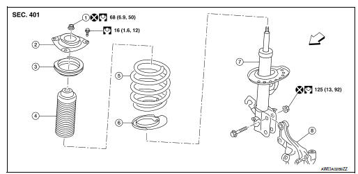
- Piston rod lock nut
- Strut mount insulator
- Strut mount bearing
- Bound bumper
- Coil spring
- Lower rubber seat
- Strut
- Steering knuckle
 Front
Front
Removal and Installation
REMOVAL
- Remove the wheel and tire using power tool. Refer to WT-47, "Exploded View".
- Remove the lock plate from the front coil spring and strut and reposition the brake hose. Refer to BR-25, "FRONT : Exploded View".
- Disconnect the stabilizer connecting rod from the front coil spring and strut. Refer to FSU-12, "Removal and Installation".
- Remove the wheel sensor bolt. Position the wheel sensor and the wheel sensor harness aside. Refer to BRC-106, "FRONT WHEEL SENSOR : Removal and Installation".
- Use a jack to support the transverse link and the steering knuckle.
- Remove the lower strut nuts and bolts (
 ).
).
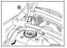
- Remove the grommet (A) from the cowl top cover.
 : Front
- Access 1 upper strut bolt through the grommet hole.
- Remove the upper strut bolts from the strut mount insulator (1).
- Remove the front coil spring and strut.
- Inspect the components. Refer to FSU-21, "Inspection".
INSTALLATION
Installation is in the reverse order of removal.
CAUTION:
Do not reuse piston rod lock nut or strut nuts.
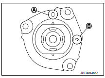
- Install the front coil spring and strut with the identification mark (A) of the strut mount insulator facing toward the front of the vehicle and the arrow (B) facing the outboard side.
NOTE:
The identification mark "0" shows the (RH) strut mount insulator and "1" shows the (LH).
- Perform the final tightening of the bolts and nuts under unladen conditions with the tires on level ground.
- Complete the inspection. Refer to FSU-21, "Inspection".
- After replacing the strut, always follow the disposal procedure to discard the old strut. Refer to FSU-22, "Disposal".

 Transverse link
Exploded View
Upper link
Front suspension member
Transverse link
Front
Removal and Installation
REMOVAL
Remove the wheel and tire using power tool. Refer to WT-47, "Explode ...
Other materials:
Ambient sensor signal circuit
Description
It detects outside air temperature and converts it into a resistance value
which is then input into the combination
meter.
Diagnosis Procedure
Regarding wiring diagram information, refer to mwi-28, "wiring diagram".
1.Check ambient sensor signal circuit
Turn igniti ...
B0020 Side airbag module LH
Description
DTC B0020 FRONT LH SIDE AIR BAG MODULE
The front LH side air bag module is wired to the air bag diagnosis sensor
unit. The air bag diagnosis sensor
unit will monitor for opens and shorts in detected lines to the front LH side
air bag module.
PART LOCATION
Refer to SRC-5, " ...
Speedometer and odometer
Speedometer
The speedometer indicates the vehicle speed.
Odometer/Twin trip odometer
The odometer 2 and the twin trip odometer 1
are displayed when the ignition switch is placed
in the ON position.
The odometer records the total distance the vehicle
has been driven.
The twin trip o ...
