Nissan Sentra Service Manual: Flywheel
Exploded View
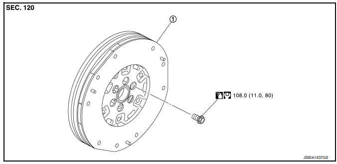
- Flywheel
Removal and Installation
REMOVAL
- Remove the engine and the transaxle assembly from the vehicle, and separate the transaxle from the engine. Refer to TM-28, "Exploded View".
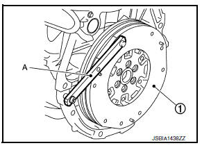
- Remove flywheel.
- Secure flywheel (1) using Tool (A), and remove bolts using suitable tool.
Tool number : KV11105210 (J-44716)
CAUTION:
- Do not disassemble flywheel.
- Do not place flywheel with signal plate facing down.
- When handling signal plate, take care not to damage or scratch.
- Handle signal plate, do so in a manner that prevents it from becoming magnetized.
INSTALLATION
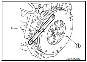
- Install flywheel.
- Secure flywheel (1) using Tool (A), and install bolts.
Tool number : KV11105210 (J-44716)
CAUTION:
Be careful not to damage or scratch the contact surface of flywheel.
Inspection
FLYWHEEL DEFLECTION
- Measure the deflection of flywheel contact surface to torque with a dial indicator (A).
- Measure the deflection at 210 mm (8.27 in) diameter.
Limit : 0.45 mm (0.0177 in) or less.
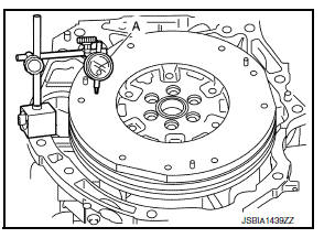
- If measured value is out of the standard, replace flywheel.
- If a trace of burn or discoloration is found on the surface, repair it with sandpaper.
MOVEMENT AMOUNT OF FLYWHEEL
CAUTION:
Do not disassemble double mass flywheel.
Movement Amount of Thrust (Fore-and-Aft) Direction
- Measure the movement amount of thrust (fore-and-aft) direction when 100 N (10.2 kg, 22 lb) force is added at the portion of 125 mm (4.92 in) radius from the center of flywheel.
Standard : 1.8 mm (0.071 in) or less
- If measured value is out of the standard, replace flywheel
Movement Amount in Radial (Rotation) Direction
Check the movement amount of radial (rotation) direction with the following procedure:
- Install clutch cover bolt (1) to clutch cover hole, and place a torque wrench (A) on the extended line of the flywheel (2) center line.
- Tighten bolt at a force of 9.8 NВ·m (1.0 kg-m, 87 in-lb) to keep it from loosening.
- Put a mating mark on circumferences of the two flywheel masses without applying any load (Measurement standard points).
- Apply a force of 9.8 NВ·m (1.0 kg-m, 87 in-lb) in each direction, and mark the movement amount on the mass on the transaxle side.
- Measure the dimensions of movement amounts (A) and (B) on circumference of the flywheel on the transaxle side.
Limit : 33.2 mm (1.307 in) or less.
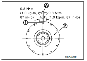
- If measured value is out of the standard, replace flywheel.

 Drive plate
Exploded View
Pilot converter
Drive plate
Reinforcement plate
Chamfered
Removal and Installation
REMOVAL
Remove the engine and the transaxle assembly from the vehicle, and
...
Other materials:
System description
Component parts
Component parts location
ABS actuator and electric unit (control
unit)
Av control unit
A/c auto amp.
Ecm
Ipdm e/r
Tcm
Data link connector
EPS control unit
Bcm
Combination meter
Steering angle sensor
Air bag diagnosis sensor unit
System
Can communi ...
Diagnosis system (ECM)
Diagnosis description : 1st trip detection
logic and two trip detection logic
When a malfunction is detected for the first time, 1st trip DTC and 1st trip
Freeze Frame data are stored in the
ECM memory. The MIL will not illuminate at this stage. <1st trip>
If the same malfunction is dete ...
Precaution for Supplemental Restraint System (SRS) "AIR BAG"
and "SEAT BELT PRE-TENSIONER"
The Supplemental Restraint System such as “AIR BAG” and “SEAT
BELT PRE-TENSIONER”, used along
with a front seat belt, helps to reduce the risk or severity of injury to the
driver and front passenger for certain
types of collision. Information necessary to service the system ...
