Nissan Sentra Service Manual: Exhaust manifold
Exploded View
CALIFORNIA
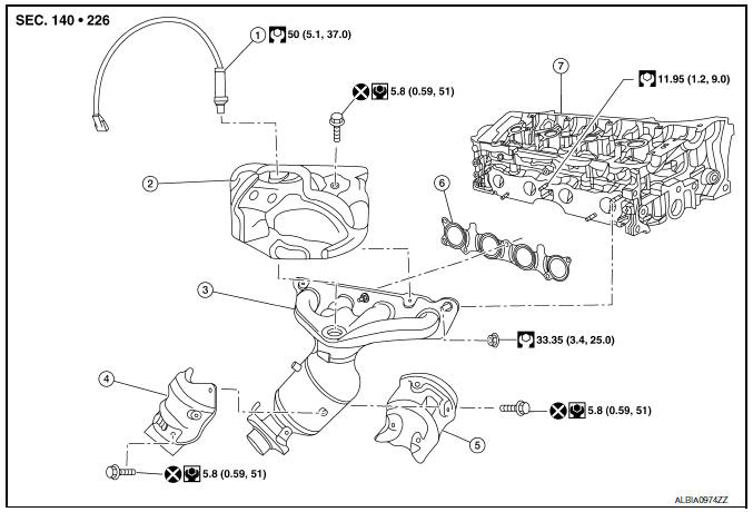
- Air fuel ratio sensor
- Exhaust manifold heat shield (upper)
- Exhaust manifold and three way catalyst
- Exhaust manifold heat shield (rear)
- Exhaust manifold heat shield (front)
- Exhaust manifold gasket
- Cylinder head
EXCEPT CALIFORNIA
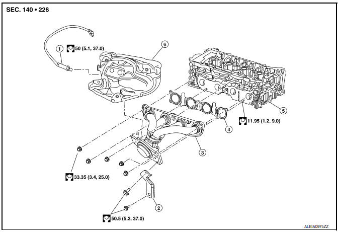
- Air fuel ratio sensor
- Bracket
- Exhaust manifold
- Exhaust manifold gasket
- Cylinder head
- Exhaust manifold heat shield
Removal and Installation
REMOVAL
- Remove the cowl top. Refer to EXT-25, "Exploded View".
- Remove front exhaust tube. Refer to EX-5, "Exploded View".
- Disconnect air fuel ratio sensor harness connector and remove air fuel ratio sensor if necessary.
- Remove exhaust manifold cover.
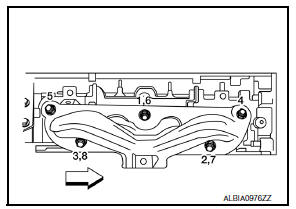
- Remove exhaust manifold.
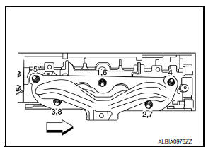
- Loosen nuts in reverse order as shown.
NOTE:
Disregard the numerical order No. 6-8 in removal.
- Remove exhaust manifold gasket.
CAUTION:
Cover engine openings to avoid entry of foreign materials.
INSTALLATION
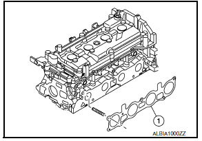
- Install exhaust manifold gasket (1) to cylinder head as shown.
CAUTION:
Do not reuse exhaust manifold gasket (1).
- Install exhaust manifold with the following procedure:
- Tighten nuts in numerical order as shown.
NOTE:
- Tighten nuts the No.1-3 in two steps.
- The numerical order No.6-8 shows the second step.
- Installation of remaining components is in the reverse order of removal.
Inspection
INSPECTION AFTER REMOVAL
Surface Distortion
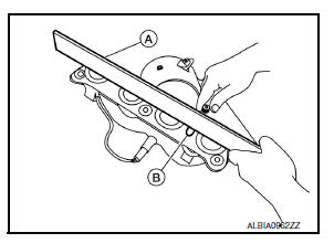
- Using feeler gauge (A) and straightedge (B), check the surface distortion of exhaust manifold mating surface in each exhaust port and entire part.
Limit : Refer to EM-119, "Exhaust Manifold".
- If it exceeds the limit, replace exhaust manifold.
 Intake manifold
Exploded View
Clamp
PCV hose
Bracket
Intake manifold gasket
Intake manifold
Mount rubber
Clamp
EVAP hose
EVAP canister purge volume
control solenoid valve
Electric throttl ...
 Oil pan
Exploded View
O-ring
Oil pan (upper)
Oil level gauge guide
O-ring
Oil level gauge
Oil pump drive chain
Crankshaft sprocket
Oil pump sprocket
Oil pump chain tensioner
Oil pump
...
Other materials:
Readiness for inspection/maintenance (I/M) test
Due to legal requirements in some states and
Canadian Provinces, your vehicle may be required
to be in what is called the “ready condition”
for an Inspection/Maintenance (I/M) test of
the emission control system.
The vehicle is set to the “ready condition” when it
is driven through c ...
Basic inspection
Diagnosis and repair work flow
Work Flow
OVERALL SEQUENCE
DETAILED FLOW
1.GET INFORMATION FOR SYMPTOM
Get detailed information from the customer about the symptom (the
condition and the environment when
the incident/malfunction occurs).
Check operation condition of the function th ...
Precaution for work
When removing or disassembling each component, be careful not to damage
or deform it. If a component
may be subject to interference, be sure to protect it with a shop cloth.
When removing (disengaging) components with a screwdriver or similar
tool, be sure to wrap the component
with a ...
