Nissan Sentra Service Manual: Except 6M/T
EXCEPT 6M/T : Exploded View
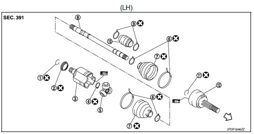
- Circular clip
- Dust shield
- Slide joint housing
- Snap ring
- Spider assembly
- Boot band
- Boot
- Shaft
- Damper band
- Dynamic damper
- Circular clip
- Joint sub-assembly
 Wheel side
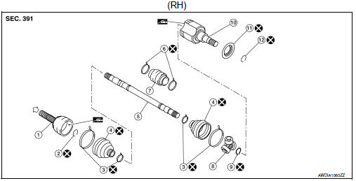
- Joint sub-assembly
- Circular clip
- Boot band
- Boot
- Shaft
- Damper band
- Dynamic damper
- Spider assembly
- Snap ring
- Slide joint housing
- Dust shield
- Circular clip
 Wheel side
EXCEPT 6M/T : Disassembly and Assembly
DISASSEMBLY (WHEEL SIDE)
- Mount the drive shaft in a vise.
CAUTION:
When mounting the drive shaft in a vise, always use aluminum or copper plates between the vise and the drive shaft.
- Remove the boot bands and slide the boot back.
- Screw a suitable tool (A) into the joint sub-assembly screw part to a length of 30 mm (1.18 in) or more. Support the drive shaft with one hand and pull out the joint sub-assembly from the shaft.
CAUTION:
- Align the suitable tool and the drive shaft. Remove the joint sub-assembly by pulling firmly and uniformly.
- If the joint sub-assembly cannot be removed after five or more attempts, replace the shaft and the joint sub-assembly as a set.
- Remove the circular clip from the shaft.
- Remove the outer boot from the shaft.
- Inspect the components. Refer to FAX-28, "EXCEPT 6M/T : Inspection".
DISASSEMBLY (TRANSAXLE SIDE)
- Mount the drive shaft in a vise.
CAUTION:
When mounting the drive shaft in a vise, always use aluminum or copper plates between the vise and the drive shaft.
- Remove the boot bands and slide the boot back.
- Put matching marks on the slide joint housing and on the shaft.
CAUTION:
Use paint or an equivalent for matching marks. Do not scratch the surfaces.
- Remove the snap ring (1).
- Remove the spider assembly from the shaft.
- Remove the inner boot from the shaft.
- Remove the dust shield from the slide joint housing.
- Remove the circular clip from the slide joint housing.
- Clean the old grease from the slide joint housing with paper waste.
- Remove the damper bands.
- Remove the dynamic damper from the shaft.
- Inspect the components. Refer to FAX-28, "EXCEPT 6M/T : Inspection".
ASSEMBLY (WHEEL SIDE)
- Clean the old grease from the joint sub-assembly using paper waste.
- Fill the serration slot on the joint sub-assembly (1) with NISSAN genuine grease or equivalent until the serration slot and ball groove become full to the brim.
CAUTION:
After applying the grease, use paper waste to wipe off the grease that has oozed out.
NOTE:
Always check with the Parts Department for the latest parts information.
- Install the outer boot and the boot bands to the shaft.
CAUTION:
- Wrap the serration on the shaft with tape (A) to protect the boot from damage.
- Do not reuse the boot.
- Do not reuse the boot bands.
- Remove the tape wrapped around the serration on the shaft.
- Position the circular clip (1) on the groove at the shaft edge.
CAUTION:
Do not reuse the circular clip.
NOTE:
A drive joint inserter is recommended when installing the circular clip.
- Align both center axles with the shaft edge and the joint subassembly.
Assemble the shaft with the joint sub-assembly while holding the circular clip.
- Install the joint sub-assembly to the shaft using a suitable tool.
CAUTION:
- Make sure the circular clip is properly positioned on the groove of the joint sub-assembly.
- Confirm that the joint sub-assembly is correctly engaged while rotating the drive shaft.
- Apply the specified amount of grease to the inside of the large diameter side of the boot.
NOTE:
Always check with the Part Department for the latest parts information.
Grease amount : Refer to FAX-49, "Drive Shaft".
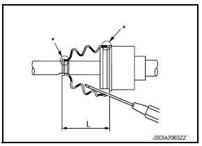
- Install the boot securely into the grooves (indicated by “*” marks) as shown.
CAUTION:
If there is grease on the boot mounting surfaces (indicated by “*” marks) on the shaft or the joint sub-assembly, the boot may come off. Remove all grease from the boot mounting surfaces.
- To prevent the deformation of the boot, adjust the boot installation length to the specified value by inserting a suitable tool into the inside of the boot from the large diameter side of the boot and discharging the inside air.
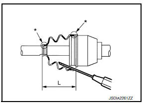
Boot installation length (L) : Refer to FAX-49, "Drive Shaft".
CAUTION:
- The boot may break if the boot installation length is not correct.
- Be careful not to touch the inside of the boot with the tip of the suitable tool.
- Install new large and small boot bands securely using Tool (A).
CAUTION:
Do not reuse the boot bands.
Tool number (A): KV40107300 ( – )
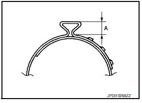
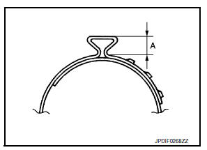
- Secure the boot band so that dimension (A) meets the specification.
Dimension (A) : Refer to FAX-49, "Drive Shaft".
- Attempt to rotate the boot to check whether or not the boot bands are securing the boot. If the boot is not secure, remove the boot bands, reposition the boot, and install new boot bands.
ASSEMBLY (TRANSAXLE SIDE)
- Install the dynamic damper using the following procedure:
- Install the dynamic damper to the shaft.
- Secure the dynamic damper in the correct position with new damper bands.
CAUTION:
Do not reuse damper bands.
Dimension (A) : Refer to FAX-49, "Drive Shaft".
- Install the inner boot and the boot bands to the shaft.
CAUTION:
- Wrap the serration on the shaft with tape (A) to protect the boot from damage.
- Do not reuse the boot.
- Do not reuse the boot bands.
- Remove the tape wrapped around the serration on the shaft.
- Align the matching mark (A) on the spider assembly (1) with the matching mark on the shaft (2). Install the spider assembly to the shaft with the chamfer (B) facing the shaft.
- Secure the spider assembly onto the shaft with the snap ring (1).
CAUTION:
Do not reuse the snap ring.
- Apply the appropriate amount of grease (Genuine NISSAN Grease or equivalent) to the spider assembly and to the sliding surface.
NOTE:
Always check with the Parts Department for the latest parts information.
- Install the slide joint housing onto the spider assembly and pack the balance of the specified amount grease (Genuine NISSAN Grease or equivalent) into the slide joint housing.
NOTE:
Always check with the Parts Department for the latest parts information.
Grease amount : Refer to FAX-49, "Drive Shaft".
- Align the matching marks on the slide joint housing and on the shaft.
- Install the boot securely into the grooves (indicated by “*” marks) as shown.
CAUTION:
If there is grease on the boot mounting surfaces (indicated by “*” marks) on the shaft or the joint sub-assembly, the boot may come off. Remove all grease from the boot mounting surfaces.
- To prevent the deformation of the boot, adjust the boot installation length to the specified value by inserting a suitable tool into the inside of the boot from the large diameter side of the boot and discharging the inside air.
Boot installation length (L) : Refer to FAX-49, "Drive Shaft".
CAUTION:
- The boot may break if the boot installation length is not correct.
- Be careful not to touch the inside of the boot with the tip of the suitable tool.
- Install the boot bands securely
CAUTION:
Do not reuse the boot bands.
For low profile type band
- Put the new boot band in the groove on the drive shaft boot. Temporarily fit the pawls into the holes.
NOTE:
For the large diameter side, fit the projection (A) into the guide slit (B).
- Pinch the projection on the band with suitable pliers to tighten the band.
- Insert the tip of the band into the lower part of the pawl (marked with dotted circle) as shown.
For omega type band
- Install new large and small boot bands securely using Tool (A).
CAUTION:
Do not reuse the boot bands.
Tool number (A): KV40107300 ( – )
- Secure the boot band so that dimension (A) meets the specification.
Dimension (A) : Refer to FAX-49, "Drive Shaft".
- Attempt to rotate the boot to check whether or not the boot bands are securing the boot. If the boot is not secure, remove the boot bands, reposition the boot, and install new boot bands.
- Install the dust shield to the slide joint housing.
CAUTION:
Do not reuse the dust shield.
- Install the circular clip to the slide joint housing.
CAUTION:
Do not reuse the circular clip.
 6M/T
6M/T
6M/T : Exploded View (LH)
Circular clip
Dust shield
Slide joint housing
Snap ring
Spider assembly
Boot band
Boot
Shaft
Damper band
Dynamic damper
Circular clip
Joint sub ...
 Service data and specifications
Wheel Bearing
Drive Shaft
Drive Shaft Specifications
*: Always check with the Parts Department for the latest parts information.
Dynamic Damper Specifications
...
Other materials:
Refrigerant
Description
CONNECTION OF SERVICE TOOLS AND EQUIPMENT
Shut-off valve
A/C service valve
Recovery/recycling/recharging
equipment
Refrigerant container (HFC-134a)
Weight scale (J-39650)
Vacuum pump (J-39649)
Manifold gauge set (J-39183)
Preferred (best) method
Alternativ ...
P1078 EVT Control position sensor
DTC Logic
DTC DETECTION LOGIC
DTC No.
CONSULT screen terms
(Trouble diagnosis content)
DTC detecting condition
Possible cause
P1078
EXH TIM SEN/CIRC-B1
(Exhaust valve timing control
position sensor circuit
bank 1)
An excessively high or low voltage from
...
Diagnosis description : system readiness
test (SRT) code
System Readiness Test (SRT) code is specified in Service $01 of SAE J1979/ISO
15031-5.
As part of an enhanced emissions test for Inspection & Maintenance (I/M),
certain states require the status of
SRT be used to indicate whether the ECM has completed self-diagnosis of major
emission s ...
