Nissan Sentra Service Manual: Engine protection control at low engine oil pressure
ENGINE PROTECTION CONTROL AT LOW ENGINE OIL PRESSURE : System Description
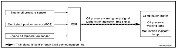
SYSTEM DIAGRAM
INPUT/OUTPUT SIGNAL CHART
| Sensor | Input signal to ECM | ECM function | Actuator |
| Engine oil pressure sensor | Engine oil pressure | Engine protection control
|
Combination meter
|
| Crankshaft position sensor (POS) | Engine speed | ||
| Engine oil temperature sensor | Engine oil temperature |
SYSTEM DESCRIPTION
- The engine protection control at low engine oil pressure warns the driver of a decrease in engine oil pressure by the oil pressure warning lamp a before the engine becomes damaged.
- When detecting a decrease in engine oil pressure at an engine speed less than 1,000 rpm, ECM transmits an oil pressure warning lamp signal to the combination meter.The combination meter turns ON the oil pressure warning lamp, according to the signal.
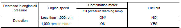
*: When detecting a normal engine oil pressure, ECM turns OFF the oil pressure warning lamp.
 Intake manifold tuning system
INTAKE MANIFOLD TUNING SYSTEM : System
Description
SYSTEM DIAGRAM
SYSTEM DESCRIPTION
This system switches the length of intake air path according to the
low-to-medium speed range or high spe ...
 Fuel filler cap warning system
SYSTEM DIAGRAM
SYSTEM DESCRIPTION
The fuel filler cap warning system alerts the driver to the prevention of the
fuel filler being left uncapped and
malfunction occurrences after refueling, by ...
Other materials:
P0101, P0102, P0103 MAF Sensor
DTC Logic
DTC DETECTION LOGIC
DTC No.
CONSULT screen terms
(Trouble diagnosis content)
DTC detecting condition
Possible cause
P0101
MAF SEN/CIRCUIT-B1
(Mass or volume air flow “A”
circuit range/performance)
An excessively high voltage from the mass ...
Wiring diagram
AUTOMATIC AIR CONDITIONING SYSTEM
Wiring Diagram
...
B terminal circuit
Description
“B” terminal circuit supplies power to charge the battery and to operate the
vehicles electrical system.
Diagnosis procedure
Regarding wiring diagram information. Refer to chg-9, "wiring diagram".
1.Check “b” terminal connection
Turn ignition switc ...
