Nissan Sentra Service Manual: Electric ignition system
ELECTRIC IGNITION SYSTEM : System Description
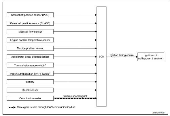
SYSTEM DIAGRAM
*1: CVT models
*2: M/T models
Input/output signal chart
| Sensor | Input Signal to ECM | ECM function | Actuator | |
| Crankshaft position sensor (POS) |
|
Ignition timing control | Ignition coil (with power transistor) | |
| Camshaft position sensor (PHASE) | ||||
| Mass air flow sensor | Amount of intake air | |||
| Engine coolant temperature sensor | Engine coolant temperature | |||
| Throttle position sensor | Throttle position | |||
| Accelerator pedal position sensor | Accelerator pedal position | |||
| Transmission range switch*1 | Gear position | |||
| Park/neutral position (PNP) switch*2 | ||||
| Battery | Battery voltage*3 | |||
| Knock sensor | Engine knocking condition | |||
| Combination meter | CAN communication | Vehicle speed signal | ||
*1: CVT models
*2: M/T models
*3: ECM determines the start signal status by the signals of engine speed and battery voltage.
SYSTEM DESCRIPTION
Firing order: 1 - 3 - 4 - 2
The ignition timing is controlled by the ECM to maintain the best air-fuel ratio for every running condition of the engine. The ignition timing data is stored in the ECM.
The ECM receives information such as the injection pulse width and camshaft position sensor (PHASE) signal.
Computing this information, ignition signals are transmitted to the power transistor.
During the following conditions, the ignition timing is revised by the ECM according to the other data stored in the ECM.
- At starting
- During warm-up
- At idle
- At low battery voltage
- During acceleration
The knock sensor retard system is designed only for emergencies. The basic ignition timing is programmed within the anti-knocking zone, if recommended fuel is used under dry conditions. The retard system does not operate under normal driving conditions. If engine knocking occurs, the knock sensor monitors the condition.
The signal is transmitted to the ECM. The ECM retards the ignition timing to eliminate the knocking condition.
 Multiport fuel injection system
MULTIPORT FUEL INJECTION SYSTEM : System
Description
SYSTEM DIAGRAM
*1: ECM determines the start signal status by the signals of engine speed and
battery voltage.
*2: M/T models
*3: CVT mod ...
 Intake valve timing control
INTAKE VALVE TIMING CONTROL : System Description
SYSTEM DIAGRAM
INPUT/OUTPUT SIGNAL CHART
Sensor
Input signal to ECM
ECM function
Actuator
Crankshaft position sensor (P ...
Other materials:
P0171 Fuel injection system function
DTC Logic
DTC DETECTION LOGIC
With the Air/Fuel Mixture Ratio Self-Learning Control, the actual mixture
ratio can be brought closely to the
theoretical mixture ratio based on the mixture ratio feedback signal from the
A/F sensors 1. The ECM calculates
the necessary compensation to correct th ...
Front combination lamp
Exploded View
Large cover (not serviceable)
Small cover (not serviceable)
Front combination lamp
Halogen lamp bulb (high beam)
Turn signal lamp bulb
Turn signal lamp bulb socket
LED harness connector
Halogen lamp bulb (high beam)
harness connector
Halogen lamp bulb (low bea ...
SPORT mode switch
Adjusts the throttle sensitivity and transmission
points (CVT only) to enhance performance. Press
the SPORT button on the instrument panel to
activate. The SPORT mode indicator light (on the
speedometer) will illuminate. The SPORT mode
indicator light will remain lit while the mode is
acti ...
