Nissan Sentra Service Manual: Ecu diagnosis information
Av control unit
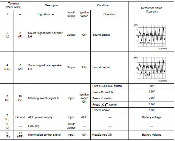
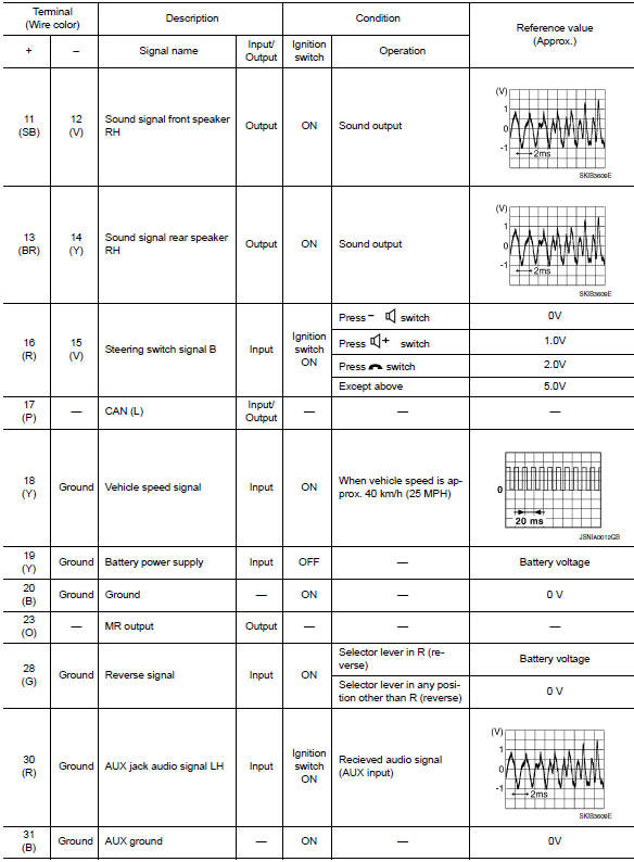
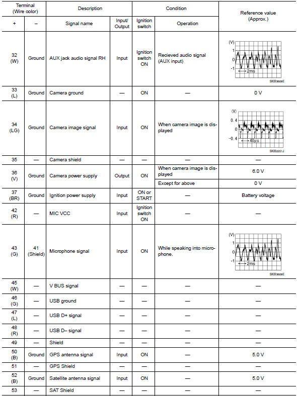
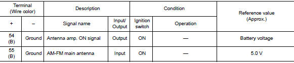
Reference value
TERMINAL LAYOUT

PHYSICAL VALUES
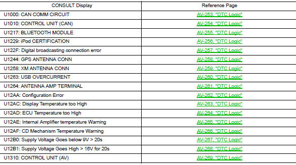
Dtc index
 System description
Component parts
Component parts location
Front tweeter lh
GPS antenna
Steering switches
Av control unit
Front tweeter rh
Microphone
Front door speaker LH
Front door speaker rh
...
 Wiring diagram
Navigation without bose
Wiring diagram
...
Other materials:
Precaution for Supplemental Restraint System (SRS) "AIR BAG" and "SEAT BELT
PRE-TENSIONER"
The Supplemental Restraint System such as ą▓ąéčÜAIR BAGą▓ąéč£ and ą▓ąéčÜSEAT BELT PRE-TENSIONERą▓ąéč£,
used along
with a front seat belt, helps to reduce the risk or severity of injury to the
driver and front passenger for certain
types of collision. Information necessary to service the system ...
Inspection and adjustment
Additional service when replacing control unit
ADDITIONAL SERVICE WHEN REPLACING CONTROL UNIT : Description
WARNING:
Always perform zero point reset using CONSULT when removing and
installing the front passenger
seat or servicing the occupant classification system. If zero point reset is not ...
Diagnosis description : counter system
RELATIONSHIP BETWEEN MIL, 1ST TRIP DTC, DTC, AND DETECTABLE ITEMS
When a malfunction is detected for the first time, the 1st trip DTC and
the 1st trip freeze frame data are
stored in the ECM memory.
When the same malfunction is detected in two consecutive trips, the DTC
and the freeze ...
