Nissan Sentra Service Manual: Eco mode control
ECO MODE CONTROL : System Description
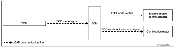
SYSTEM DIAGRAM
SYSTEM DESCRIPTION
- ECM receives an ECO mode signal from combination meter via CAN communication and improves the fuel economy by controlling the throttle movement to less than usual. Therefore, driving characteristic is controlled (reducing energy consumption by decreasing needless acceleration and deceleration), so that driving that improved operational fuel efficiency is assisted.
- ECM receives an ECO mode signal from TCM via CAN communication and improves the fuel economy by controlling the throttle movement to less than usual.
- ECM transmits an ECO mode indicator lamp signal to the combination meter via CAN communication.
NOTE:
For the details of the ECO mode, refer to DMS-26, "ECO MODE CONTROL : System Description" (CVT models) or DMS-6, "ECO MODE CONTROL : System Description" (M/T models).
 Can communication
CAN COMMUNICATION : System Description
CAN (Controller Area Network) is a serial communication line for real time
application. It is an on-vehicle multiplex
communication line with high data commu ...
 Sport mode control
SPORT MODE CONTROL : System Description
SYSTEM DIAGRAM
SYSTEM DESCRIPTION
SPORT mode that keeps high engine revolution and provides direct feel
and acceleration performance suitable
for ...
Other materials:
B0028 Side airbag module RH
Description
DTC B0028 FRONT RH SIDE AIR BAG MODULE
The front RH side air bag module is wired to the air bag diagnosis sensor
unit. The air bag diagnosis sensor
unit will monitor for opens and shorts in detected lines to the front RH side
air bag module.
PART LOCATION
Refer to SRC-5, " ...
C1115 ABS Sensor [abnormal signal]
DTC Logic
DTC DETECTION LOGIC
DTC
Display Item
Malfunction detected condition
Possible causes
C1115
ABS SENSOR
[ABNORMAL SIGNAL]
When difference in wheel speed between any wheel
and others is detected while the vehicle is driven, because
of installation of t ...
Tire equipment
SUMMER tires have a tread designed to
provide superior performance on dry pavement.
However, the performance of these
tires will be substantially reduced in snowy
and icy conditions. If you operate your vehicle
on snowy or icy roads, NISSAN recommends
the use of MUD & SNOW or ALL
...
