Nissan Sentra Service Manual: Dtc/circuit diagnosis
Power supply and ground circuit
Audio unit
Audio unit : diagnosis procedure
Regarding Wiring Diagram information, refer to AV-157, "Wiring Diagram".
1.Check fuse
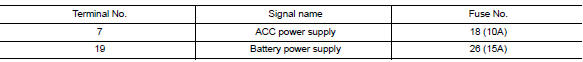
Are the fuses blown? Yes >> replace the blown fuse after repairing the affected circuit.
No >> go to 2.
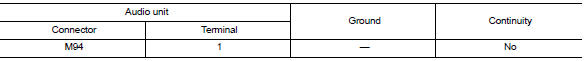
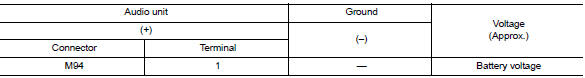
2.Check power supply circuit
- Turn ignition switch OFF.
- Disconnect audio unit connector M94.
- Check voltage between audio unit connector m94 and ground.
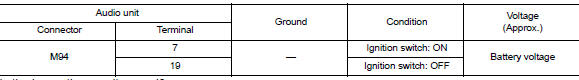
Is the inspection result normal? YES >> GO TO 3.
NO >> Repair or replace harness or connectors.
Is the inspection result normal? YES >> GO TO 3.
NO >> Repair or replace harness or connectors.
3.Check ground circuit
- Turn ignition switch OFF.
- Disconnect audio unit connector M95.
- Check continuity between audio unit connectors and ground.
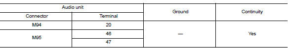
Is the inspection result normal? YES >> Inspection End.
NO >> Repair or replace harness or connectors.
Bose speaker amp
Bose speaker amp : diagnosis procedure
Regarding Wiring Diagram information, refer to AV-157, "Wiring Diagram".
1.Check fuse
Check that the following fuses are not blown.
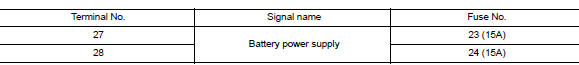
Are the fuses blown? Yes >> replace the blown fuse after repairing the affected circuit.
No >> go to 2.
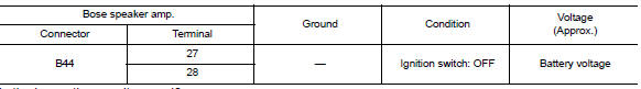
2.Check power supply circuit
- Turn ignition switch off.
- Disconnect Bose speaker amp. connector B44.
- Check voltage between bose speaker amp. Connector b44 and ground.
Is the inspection result normal? YES >> GO TO 3.
NO >> Repair or replace harness or connectors.
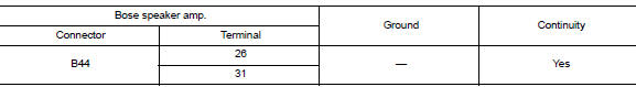
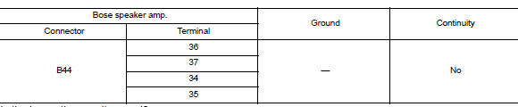
3.Check ground circuit
- Turn ignition switch OFF.
- Disconnect bose speaker amp. Connector b44.
- Check continuity between bose speaker amp. Connector b44 and ground.
Is the inspection result normal? Yes >> inspection end.
No >> repair or replace harness or connectors.
BluetoothВ® control unit
BluetoothВ® control unit : diagnosis procedure
Regarding Wiring Diagram information, refer to AV-157, "Wiring Diagram".
1.Check fuse
Check that the following fuses are not blown.
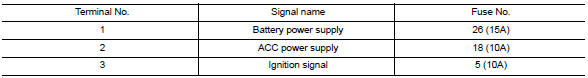
Are the fuses blown?
YES >> Replace the blown fuse after repairing the affected circuit.
NO >> GO TO 2.
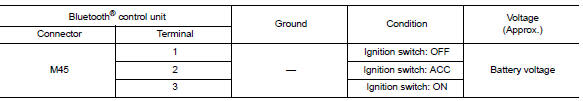
2.Check power supply circuit
- Turn ignition switch off.
- Disconnect BluetoothВ® control unit connector M45.
- Check voltage between bluetoothВ® control unit connector m45 and ground.
Is the inspection result normal? Yes >> go to 3.
No >> repair or replace harness or connectors.
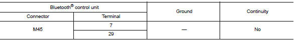
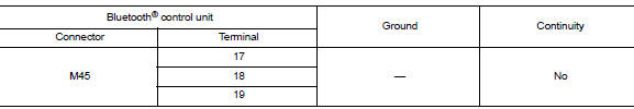
3.Check ground circuit
- Turn ignition switch off.
- Check continuity between bluetoothВ® control unit connector m45 and ground.
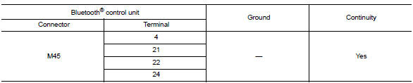
Is the inspection result normal? Yes >> inspection end.
No >> repair or replace harness or connectors.
Front door speaker
Diagnosis procedure
Regarding wiring diagram information, refer to av-157, "wiring diagram".
1.Connector check
Check the audio unit, bose speaker amp. And speaker connectors for the following:
- Proper connection
- Damage
- Disconnected or loose terminals
Is the inspection result normal? YES >> GO TO 2
No >> repair the terminals or connectors.
2.Check front door speaker signal circuit continuity (bose speaker amp.)
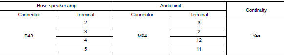
- Disconnect bose speaker amp. Connector b43 and suspect front door speaker connector.
- Check continuity between bose speaker amp. Connector b43 and suspect front door speaker connector.
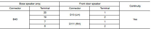
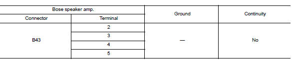
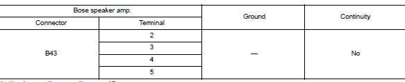
- Check continuity between bose speaker amp. Connector b43 and ground.
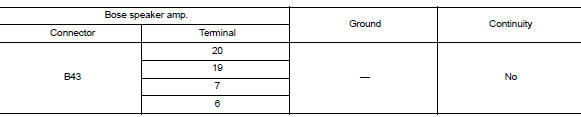
Is the inspection result normal? YES >> GO TO 3
No >> repair or replace harness or connectors.
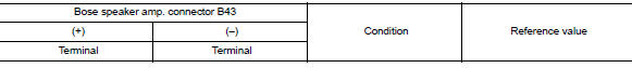
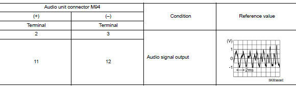
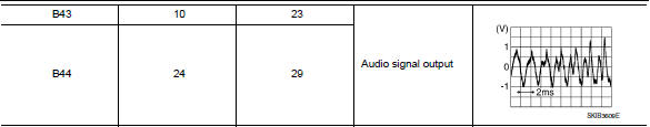
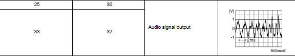
3.Check front door speaker signal (bose speaker amp.)
- Connect Bose speaker amp. connector B43 and suspect front door speaker connector.
- Turn ignition switch to ACC.
- Push audio unit power switch.
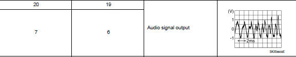
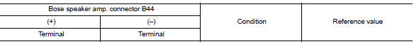
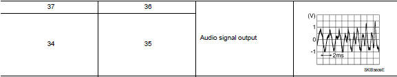
- Check signal between the terminals of bose speaker amp. Connector b43.
Is the inspection result normal? YES >> Replace front door speaker. Refer to AV-205, "Removal and Installation".
NO >> GO TO 4
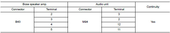
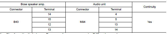
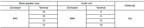
4.Check front door speaker signal circuit continuity (audio unit)
- Turn ignition switch to OFF.
- Disconnect bose speaker amp. Connector b43 and audio unit connector m94.
- Check continuity between bose speaker amp. Connector b43 and audio unit connector m94.
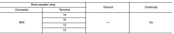
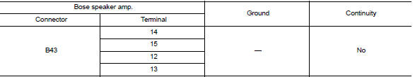
- Check continuity between bose speaker amp. Connector b43 and ground.
Is the inspection result normal? Yes >> go to 5
NO >> Repair or replace harness or connectors.
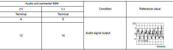
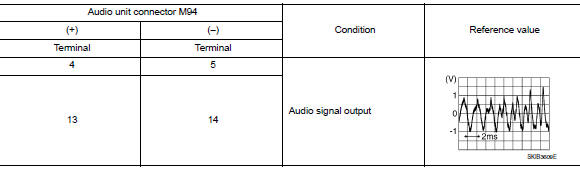
5.Check front door speaker signal (audio unit)
- Connect bose speaker amp. Connector b43 and audio unit connector m94.
- Turn ignition switch to ACC.
- Push audio unit POWER switch.
- Check signal between the terminals of audio unit connector m94.

Is the inspection result normal?
YES >> Replace Bose speaker amp. Refer to AV-214, "Removal and Installation".
NO >> Replace audio unit. Refer to AV-203, "Removal and Installation".
Front tweeter
Diagnosis Procedure
Regarding Wiring Diagram information, refer to AV-157, "Wiring Diagram".
1.Connector check
Check the audio unit, Bose speaker amp. and speaker connectors for the following:
- Proper connection
- Damage
- Disconnected or loose terminals
Is the inspection result normal? Yes >> go to 2
NO >> Repair the terminals or connectors.
2.Check front tweeter signal circuit continuity (bose speaker amp.)
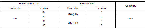
- Disconnect Bose speaker amp. connector B44 and suspect front tweeter connector.
- Check continuity between bose speaker amp. Connector b44 and suspect front tweeter connector.
- Check continuity between Bose speaker amp. connector B44 and ground.
Is the inspection result normal? YES >> GO TO 3
No >> repair or replace harness or connectors.
3.Check front tweeter signal (bose speaker amp.)
- Connect Bose speaker amp. connector B44 and suspect front tweeter connector.
- Turn ignition switch to ACC.
- Push audio unit power switch.
- Check signal between the terminals of Bose speaker amp. connector B44.
Is the inspection result normal? YES >> Replace front tweeter. Refer to AV-204, "Removal and Installation".
NO >> GO TO 4
4.Check front tweeter signal circuit continuity (audio unit)
- Turn ignition switch to off.
- Disconnect bose speaker amp. Connector b43 and audio unit connector m94.
- Check continuity between bose speaker amp. Connector b43 and audio unit connector m94.
- Check continuity between bose speaker amp. Connector b43 and ground.
Is the inspection result normal? Yes >> go to 5
No >> repair or replace harness or connectors.
5.Check front tweeter signal (audio unit)
- Connect Bose speaker amp. connector B43 and audio unit connector M94.
- Turn ignition switch to ACC
- Push audio unit POWER switch.
- Check signal between the terminals of audio unit connector m94.
Is the inspection result normal?
Yes >> replace bose speaker amp. Refer to av-214, "removal and installation".
No >> replace audio unit. Refer to av-203, "removal and installation".
Rear door speaker
Diagnosis procedure
Regarding wiring diagram information, refer to av-157, "wiring diagram".
1.Connector check
Check the audio unit, Bose speaker amp. and speaker connectors for the following:
- Proper connection
- Damage
- Disconnected or loose terminals
Is the inspection result normal? YES >> GO TO 2
No >> repair the terminals or connectors.
2.Check rear door speaker signal circuit continuity (bose speaker amp.)
- Disconnect bose speaker amp. Connectors and suspect rear door speaker connector.
- Check continuity between Bose speaker amp. connectors and suspect rear door speaker connector.
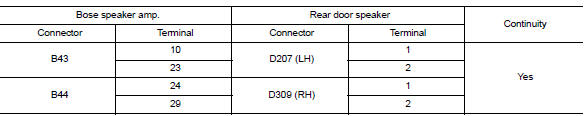
- Check continuity between bose speaker amp. Connectors and ground.
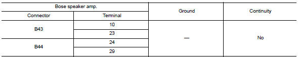
Is the inspection result normal? Yes >> go to 3
No >> repair or replace harness or connectors.
3.Check rear door speaker signal (bose speaker amp.)
- Connect bose speaker amp. Connectors and suspect rear door speaker connector.
- Turn ignition switch to acc.
- Push audio unit power switch.
- Check signal between the terminals of Bose speaker amp. connectors.
Is the inspection result normal? YES >> Replace rear door speaker. Refer to AV-206, "Removal and Installation".
NO >> GO TO 4
4.Check rear door speaker signal circuit continuity (audio unit)
- Turn ignition switch to off.
- Disconnect Bose speaker amp. connector B43 and audio unit connector M94.
- Check continuity between bose speaker amp. Connector b43 and audio unit connector m94.
- Check continuity between bose speaker amp. Connector b43 and ground.
Is the inspection result normal? Yes >> go to 5
No >> repair or replace harness or connectors.
5.Check rear door speaker signal (audio unit)
- Connect bose speaker amp. Connector b43 and audio unit connector m94.
- Turn ignition switch to acc.
- Push audio unit POWER switch.
- Check signal between the terminals of audio unit connector M94.
Is the inspection result normal?
Yes >> replace bose speaker amp. Refer to av-214, "removal and installation".
No >> replace audio unit. Refer to av-203, "removal and installation".
Rear woofer
Diagnosis procedure
Regarding wiring diagram information, refer to av-157, "wiring diagram".
1.Connector check
Check the audio unit, bose speaker amp. And speaker connectors for the following:
- Proper connection
- Damage
- Disconnected or loose terminals
Is the inspection result normal? YES >> GO TO 2
No >> repair the terminals or connectors.
2.Check rear woofer signal circuit continuity (bose speaker amp.)
- Disconnect bose speaker amp. Connector b44 and suspect rear woofer connector.
- Check continuity between Bose speaker amp. connector B44 and suspect rear woofer connector.
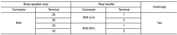
- Check continuity between bose speaker amp. Connector b44 and ground.
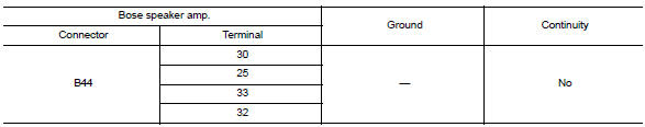
Is the inspection result normal? Yes >> go to 3
No >> repair or replace harness or connectors.
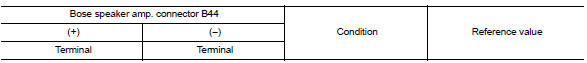
3.Check rear woofer signal (bose speaker amp.)
- Connect bose speaker amp. Connector b44 and suspect rear woofer connector.
- Turn ignition switch to ACC.
- Push audio unit POWER switch.
- Check signal between the terminals of bose speaker amp. Connector b44.
Is the inspection result normal? YES >> Replace rear woofer. Refer to AV-207, "Removal and Installation".
NO >> GO TO 4
4.Check rear woofer signal circuit continuity (audio unit)
- Turn ignition switch to off.
- Disconnect Bose speaker amp. connector B43 and audio unit connector M94.
- Check continuity between bose speaker amp. Connector b43 and audio unit connector m94.
- Check continuity between Bose speaker amp. connector B43 and ground.
Is the inspection result normal? Yes >> go to 5
No >> repair or replace harness or connectors.
5.Check rear woofer signal (audio unit)
- Connect bose speaker amp. Connector b43 and audio unit connector m94.
- Turn ignition switch to ACC.
- Push audio unit POWER switch.
- Check signal between the terminals of audio unit connector m94.
Is the inspection result normal?
Yes >> replace bose speaker amp. Refer to av-214, "removal and installation".
No >> replace audio unit. Refer to av-203, "removal and installation".
Amp on signal circuit
Diagnosis procedure
Regarding wiring diagram information, refer to av-157, "wiring diagram".
1.Check continuity between audio unit and bose speaker amp.
- Turn ignition switch off.
- Disconnect audio unit connector M94 and Bose speaker amp. connector B43.
- Check continuity between audio unit connector m94 and bose speaker amp. Connector b43.

- Check continuity between audio unit connector m94 and ground.
Is the inspection result normal? Yes >> go to 2.
No >> repair or replace harness or connectors.
2.Check audio unit voltage
- Connect audio unit connector M94.
- Turn ignition switch on.
- Check voltage between audio unit connector m94 and ground.
Is the inspection result normal? Yes >> replace bose speaker amp. Refer to av-214, "removal and installation".
No >> replace audio unit. Refer to av-203, "removal and installation".
BLUETOOTHВ® VOICE SIGNAL CIRCUIT
Diagnosis procedure
Regarding Wiring Diagram information, refer to AV-157, "Wiring Diagram".
1.Check bluetoothВ® voice signal circuit continuity
- Turn ignition switch OFF.
- Disconnect audio unit connector m95 and bluetoothВ® control unit connector m45.
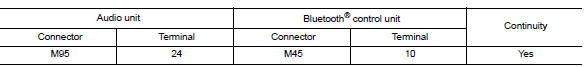
- Check continuity between audio unit connector M95 and BluetoothВ® control unit connector M45.
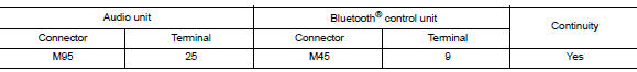
- Check continuity between audio unit connector m95 and ground.
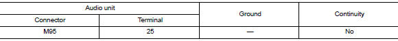
Is inspection result normal? YES >> GO TO 2.
NO >> Repair or replace harness or connectors.
2.Check bluetoothВ® voice signal ground circuit continuity
Check continuity between audio unit connector m95 and bluetoothВ® control unit connector m45.
Is inspection result normal? Yes >> go to 3.
No >> repair or replace harness or connectors.
3.Check bluetoothВ® voice signal
- Connect audio unit connector m95 and bluetoothВ® control unit connector m45.
- Turn ignition switch to acc.
- Press

switch. - Check signal between the terminals of audio unit connector M95.
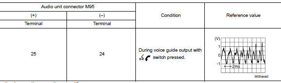
Is the inspection result normal? Yes >> replace bluetoothВ® control unit. Refer to av-217, "removal and installation".
No >> replace audio unit. Refer to av-203, "removal and installation".
BluetoothВ® control signal circuit
Diagnosis procedure
Regarding Wiring Diagram information, refer to AV-157, "Wiring Diagram".
1.Check control signal circuit continuity
- Turn ignition switch off.
- Disconnect bluetoothВ® control unit connector m45.
- Check continuity between BluetoothВ® control unit connector M45 and ground.
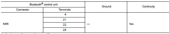
Is the inspection result normal? YES >> Replace BluetoothВ® control unit. Refer to AV-217, "Removal and Installation".
NO >> Repair or replace harness or connectors.
Microphone signal circuit
Diagnosis procedure
Regarding wiring diagram information, refer to av-157, "wiring diagram".
1.Check harness between bluetoothВ® control unit and microphone
- Turn ignition switch off.
- Disconnect bluetoothВ® control unit connector m45 and microphone connector r4.
- Check continuity between bluetoothВ® control unit connector m45 and microphone connector r4.
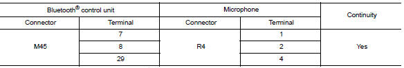
- Check continuity between bluetoothВ® control unit connector m45 and ground.
Are continuity results as specified? YES >> GO TO 2
No >> repair harness or connectors.
2.Check microphone power supply
- Connect BluetoothВ® control unit connector M45 and microphone connector R4.
- Turn ignition switch ON.
- Check voltage between microphone connector r4 and ground.
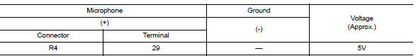
Is the voltage reading as specified? Yes >> go to 3
NO >> Replace BluetoothВ® control unit. Refer to AV-217, "Removal and Installation".
3.Check microphone signal
Check signal between terminals of bluetoothВ® control unit connector m45.
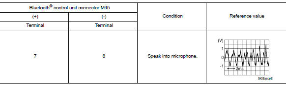
Were voltage readings as specified? Yes >> replace bluetoothВ® control unit. Refer to av-217, "removal and installation".
No >> replace microphone. Refer to av-218, "removal and installation".
Steering switch
Diagnosis Procedure
Regarding wiring diagram information, refer to av-157, "wiring diagram".
1.Check steering wheel audio control switch resistance
- Turn ignition switch OFF.
- Disconnect combination switch (spiral cable) connector m79.
- Check resistance between the terminals of combination switch (spiral cable) connector m79.
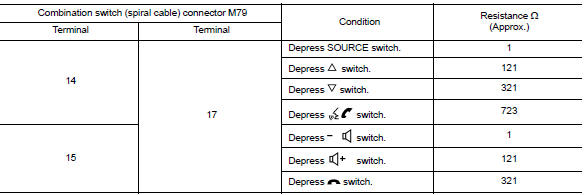
Is the inspection result normal? Yes >> go to 2.
No >> replace steering switches. Refer to av-208, "removal and installation".
2.Check harness between bluetoothВ® control unit and combination switch (spiral cable)
- Disconnect BluetoothВ® control unit connector M45 and combination switch (spiral cable) connector M80.
- Check continuity between BluetoothВ® control unit connector M45 and combination switch (spiral cable) connector M80.
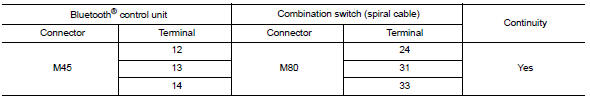
- Check continuity between BluetoothВ® control unit connector M45 and ground.
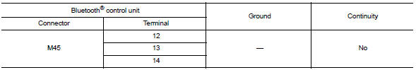
Is the inspection result normal? YES >> GO TO 3.
NO >> Repair or replace harness or connectors.
3.Check combination switch (spiral cable)
Check continuity between combination switch (spiral cable) connectors M79 and M80.
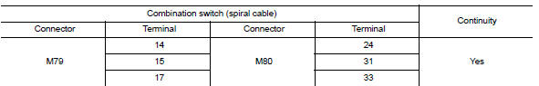
Is the inspection result normal? YES >> GO TO 4.
NO >> Replace combination switch (spiral cable). Refer to SR-16, "Removal and Installation".
4.Check harness between bluetoothВ® control unit and audio unit
- Disconnect audio unit connector m92.
- Check continuity between bluetoothВ® control unit connector m45 and audio unit connector m94.
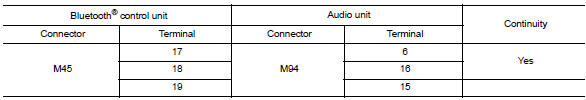
- Check continuity between bluetoothВ® control unit connector m45 and ground.
Is the inspection result normal? Yes >> replace audio unit. Refer to av-203, "removal and installation".
No >> repair or replace harness or connectors.
Usb connector
Diagnosis Procedure
Regarding Wiring Diagram information, refer to AV-157, "Wiring Diagram".
1.Check usb interface harness continuity
- Turn ignition switch OFF.
- Disconnect audio unit connector m96 and usb interface connector m132.
- Check continuity between audio unit connector M96 and USB interface connector M132.
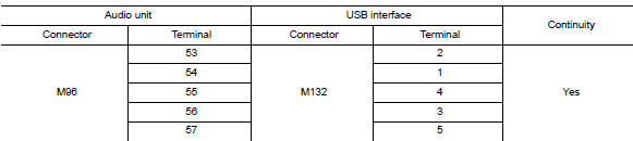
- Check continuity between audio unit connector m96 and ground.
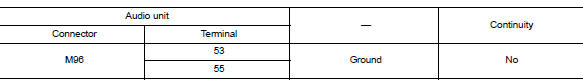
Is the inspection result normal? YES >> Replace the USB interface. Refer to AV-215, "Removal and Installation".
NO >> Repair or replace harness or connectors.
 Basic inspection
Diagnosis and repair workflow
Work flow
Overall sequence
Detailed flow
1.Get information for symptom
Get detailed information from the customer about the symptom (the condition
and the envi ...
 Symptom diagnosis
Audio system
Symptom table
Related to audio
Related to hands-free phone
Before performing diagnosis, confirm that the cellular phone being used
by the customer is compatible with ...
Other materials:
Removal and installation
Generator
Exploded view
Thermostat housing
Generator bolt (upper)
Generator bolt (lower)
Generator
B” terminal harness
“B” terminal nut
Generator harness connector
Front
Removal and installation
Note:
When removing components such as hoses,tubes\lines,etc,ca ...
P0031, P0032 A/F sensor 1 Heater
DTC Logic
DTC DETECTION LOGIC
DTC No.
CONSULT screen terms
(Trouble diagnosis content)
DTC detecting condition
Possible cause
P0031
A/F SEN 1 HTR (B1)
(HO2S heater control circuit
low bank 1 sensor 1)
The current amperage in the A/F sensor 1 heater
circui ...
P0011 IVT control
DTC Logic
DTC DETECTION LOGIC
NOTE:
If DTC P0011 is displayed with DTC P0075, first perform the trouble
diagnosis for EC-180, "DTC Logic".
DTC No.
CONSULT screen terms
(Trouble diagnosis content)
DTC detecting condition
Possible cause
P0011
INT/V TIM CO ...
