Nissan Sentra Service Manual: Door handle
Front door handle
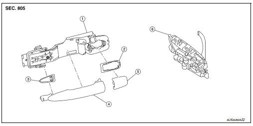
Front door handle : exploded view
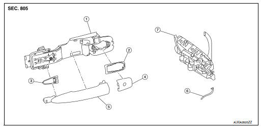
- Outside handle bracket
- Rear gasket
- Front gasket
- Outside handle escutcheon
- Outside handle
- Door key cylinder rod
- Inside handle assembly
Front door handle : removal and installation - inside handle
REMOVAL
- Remove front door finisher. Refer to INT-15, "Removal and Installation".
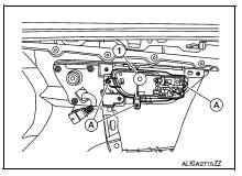
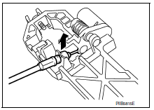
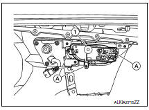
- Remove inside handle assembly screws (A) and the inside handle assembly (1).
INSTALLATION
Installation is in the reverse order of removal.
CAUTION:
- Check front door lock cables are properly engaged to inside handle.
- After installation, check front door open/close, lock/unlock operation.
Front door handle : removal and installation - outside handle
REMOVAL
- Fully close front door glass.
- Remove front door finisher. Refer to INT-15, "Removal and Installation".
- Remove front door vapor barrier.
- Remove front door glass channel rear.
- Disconnect the harness connectors from the door antenna and door request switch and then remove harness clamp on outside handle bracket.
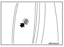
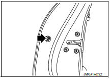
- Remove door side grommet, and loosen screw that retains the front door outside handle bracket.
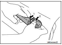
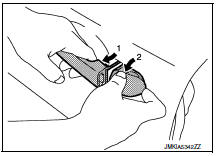
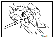
- Reach in to separate door key cylinder rod (LH side) (1) from door key cylinder assembly (LH side).
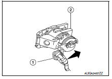
- While pulling outside handle (1), remove door key cylinder assembly (LH side) or outside handle escutcheon (2) (RH side).
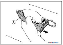
- While pulling outside handle (1), slide toward rear of vehicle to remove outside handle.
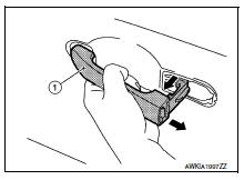
- Remove front gasket (1) and rear gasket (2).
 Front
Front
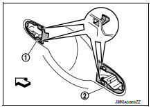
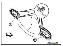
- Slide outside handle bracket toward rear of vehicle to remove.
 Front
Front
- Disconnect the outside handle cable from the outside handle bracket connection.
INSTALLATION
Installation is in the reverse order of removal.
CAUTION:
- When installing do not reuse front door outside handle bracket screw. Always replace screw with new ones when removed.
- When installing door key cylinder rod on the LH front door, be sure to rotate door key cylinder rod holder until a click is felt.
- Check front door lock cable is properly engaged to outside handle bracket.
- After installation, check front door open/close, lock/unlock operation.
Rear door handle
Rear door handle : exploded view
- Outside handle bracket
- Rear gasket
- Front gasket
- Outside door handle
- Outside handle escutcheon
- Inside handle assembly
Rear door handle : removal and installation - inside handle
REMOVAL
- Remove rear door finisher. Refer to INT-19, "Removal and Installation".
- Remove inside handle assembly screws (A) and inside handle assembly (1).
INSTALLATION
Installation is in the reverse order of removal.
CAUTION:
- Check rear door lock cables are properly engaged to inside handle.
- After installation, check rear door open/close, lock/unlock operation.
Rear door handle : removal and installation - outside handle
REMOVAL
- Fully close rear door glass.
- Remove rear door finisher. Refer to INT-19, "Removal and Installation".
- Remove rear door vapor barrier.
- Remove door side grommet, and loosen screw that retains the rear door outside handle bracket.
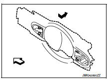
- While pulling outside handle (1), remove outside handle escutcheon (2).
- While pulling outside handle (1), slide toward rear of vehicle to remove outside handle.
- Remove front gasket (1) and rear gasket (2).
 : Front
- Slide outside handle bracket toward rear of vehicle to remove.
 : Front
- Remove clip and disconnect the outside handle cable from the outside handle bracket.
INSTALLATION
Installation in the reverse order of removal.
CAUTION:
- When installing do not reuse rear door outside handle bracket screw. Always replace screw with new ones when removed.
- Check rear door lock cable is properly engaged to outside handle bracket.
- After installation, check rear door open/close, lock/unlock operation.
 Rear door
Door assembly
Door assembly : removal and installation
Caution:
Use two people when removing or installing the rear door assembly
due to its heavy weight.
When removing and installing rear ...
 Door lock
Front door lock
Front door lock : exploded view
Outside handle bracket
Front gasket
Outside handle
Door lock assembly
Door striker
Door key cylinder rod
Inside handle assembly
Ou ...
Other materials:
Basic inspection
Diagnosis and repair work flow
Work flow
OVERALL SEQUENCE
Detailed flow
1.Get information for symptom
Get detailed information from the customer about the symptom (the
condition and the environment when
the incident/malfunction occurs)
Check operation condition of the function tha ...
Getting started
The following procedures will help you get
started using the Bluetooth® Hands-Free Phone
System with NISSAN Voice Recognition. For additional
command options, refer to “List of voice
commands” in this section.
Choosing a language
You can interact with the Bluetooth® Hands-
Free Phone Sy ...
Precautions for Suspension
When installing rubber bushings, the final tightening must be carried
out under unladen conditions with tires
on ground. Spilled oil might shorten the life of rubber bushings. Be sure to
wipe off any spilled oil.
Unladen conditions mean that fuel, engine coolant and lubricant are
...
