Nissan Sentra Owners Manual: Difference between predicted and actual distances
The distance guide line and the vehicle width guide line should be used as a reference only when the vehicle is on a level, paved surface. The distance viewed on the monitor is for reference only and may be different than the actual distance between the vehicle and displayed objects.
Backing up on a steep uphill
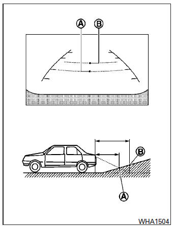
When backing up the vehicle up a hill, the distance guide lines and the vehicle width guide lines are shown closer than the actual distance.
For example, the display shows 3 ft (1.0 m) to the place A , but the actual 3 ft (1.0 m) distance on the hill is the place B . Note that any object on the hill is further than it appears on the monitor.
Backing up on a steep downhill
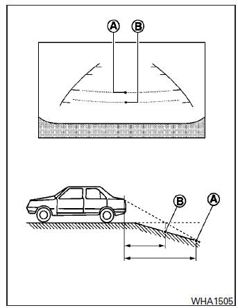
When backing up the vehicle down a hill, the distance guide lines and the vehicle width guide lines are shown farther than the actual distance.
For example, the display shows 3 ft (1.0 m) to the place A , but the actual 3 ft (1.0 m) distance on the hill is the place B . Note that any object on the hill is closer than it appears on the monitor.
Backing up behind a projecting object
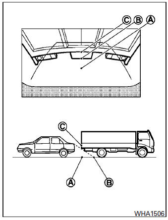
The position C is shown farther than the position B in the display. However, the position C is actually at the same distance as the position A .
The vehicle may hit the object when backing up to the position A if the object projects over the actual backing up course.
 How to read the displayed lines
Guiding lines which indicate the vehicle width
and distances to objects with reference to the
vehicle body line A are displayed on the monitor.
Distance guide lines:
Indicate distances from th ...
 Adjusting the screen
Without Navigation System
The procedure for adjusting the quality of the
screen differs depending on the type of screen
present on the vehicle.
For vehicles without Navigation System:
Pr ...
Other materials:
Secondary speed sensor
Exploded View
Transaxle assembly
O-ring
Secondary speed sensor
Vehicle front
Always replace after every
disassembly.
: NВ·m (kg-m, in-lb)
: Genuine NISSAN CVT Fluid NS-3
Removal and Installation
REMOVAL
Disconnect the secondary speed sensor connector.
Remove the s ...
Control panel buttons — color screen with Navigation System (if so equipped)
WARNING
Positioning of the heating or air conditioning
controls and display controls
should not be done while driving in order
that full attention may be given to
the driving operation.
Do not disassemble or modify this system.
If you do, it may result in acciden ...
Vehicle identification number (VIN) plate
The vehicle identification number (VIN) plate is
attached as shown. This number is the identification
for your vehicle and is used in the vehicle
registration.
Vehicle identification number (chassis number)
The vehicle identification number is located as
shown.
Engine serial number
...
