Nissan Sentra Service Manual: Description
| Number | Item | Description |
| 1 | Power supply |
|
| 2 | Fusible link |
|
| 3 | Number of fusible link/ fuse |
|
| 4 | Fuse |
|
| 5 | Current rating of fusible link/fuse |
|
| 6 | Optional splice |
|
| 7 | Connector number |
|
| 8 | Splice |
|
| 9 | Page crossing |
|
| 10 | Option abbreviation |
|
| 11 | Relay |
|
| 12 | Option description |
|
| 13 | Switch |
|
| 14 | Circuit (Wiring) |
|
| 15 | System branch |
|
| 16 | Shielded line |
|
| 17 | Component name |
|
| 18 | Ground (GND) |
|
| 19 | Connector |
|
| 20 | Connectors |
|
| 21 | Wire color |
|
| B = Black W = White R = Red G = Green L = Blue Y = Yellow LG = Light Green BG = Beige BR = Brown LA = Lavender OR or O = Orange P = Pink PU or V (Violet) = Purple GY or GR = Gray SB = Sky Blue CH = Dark Brown DG = Dark Green |
||
|
||
| 22 | Terminal number |
|

 ”.
”.Switch positions
Switches are shown in wiring diagrams as if the vehicle is in the “normal” condition.
A vehicle is in the “normal” condition when:
- ignition switch is “OFF”,
- doors, hood and trunk lid/back door are closed,
- pedals are not depressed, and
- parking brake is released.
Multiple switch
The continuity of multiple switch is described in two ways as shown below.
- The switch chart is used in schematic diagrams.
- The switch diagram is used in wiring diagrams.
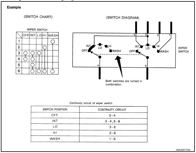
 Sample/wiring diagram -example-
For detail, refer to following GI-11, "Description".
...
 Abbreviations
Abbreviation List
The following ABBREVIATIONS are used:
A
ABBREVIATION
DESCRIPTION
A/C
Air conditioner
A/C
Air conditioning
A/F sensor
Air fuel ...
Other materials:
Basic inspection
Inspection and adjustment
Additional service when replacing control unit (bcm)
ADDITIONAL SERVICE WHEN REPLACING CONTROL UNIT (BCM) : Description
Before replacement
When replacing bcm, save or print current vehicle specification with consult
configuration before replacement.
Note:
If “B ...
Storage pouch
A storage pouch is located on the front of the
driver’s and passenger’s seats.
WARNING
Do not store angular, sharp, heavy objects
or objects that cannot fully fit inside
the pouch because they might increase
the likelihood of an injury in a
crash.
To ensure ...
Electric ignition system
ELECTRIC IGNITION SYSTEM : System Description
SYSTEM DIAGRAM
*1: CVT models
*2: M/T models
Input/output signal chart
Sensor
Input Signal to ECM
ECM function
Actuator
Crankshaft position sensor (POS)
Engine speed*3
Piston position
Ignition ...
