Nissan Sentra Service Manual: Control cable
Exploded View
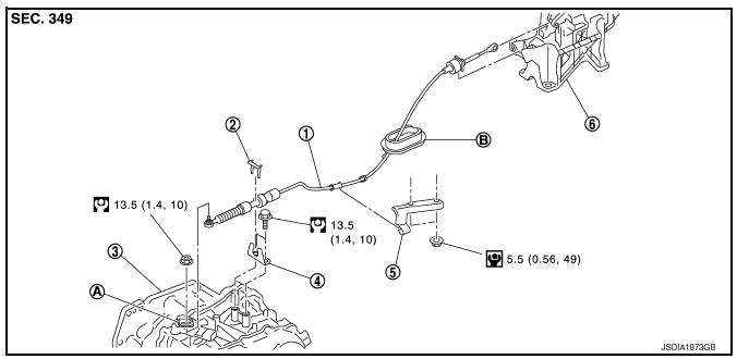
- Control cable
- Lock plate
- Transaxle assembly
- Bracket A
- Bracket B
- CVT shift selector assembly
- Manual lever
- Grommet
Removal and Installation
INSTALLATION
CAUTION:
Always apply the parking brake before performing removal and installation.
- Apply the parking brake.
CAUTION:
Make sure the vehicle cannot move with the parking brake applied.
- Remove the center console assembly. Refer to IP-17, "Removal and Installation".
- Move the shift selector to “P” position
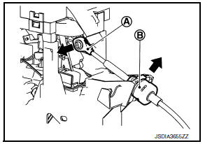
- Remove the control cable from the shift selector assembly with the following procedure.
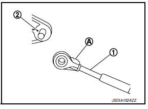
- Disconnect the tip (A) of control cable from the shift selector assembly.
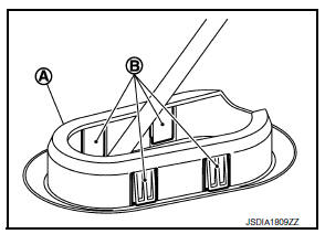
- Remove socket (B) from shift selector assembly.
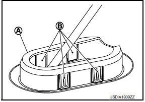
- Disengage the pawls (B) of the grommet (A), and pull downwards to remove.
- Remove the battery. Refer to PG-50, "Removal and Installation (Battery)".
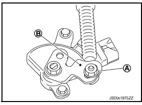
- Remove the control cable installation nut (A) from the manual lever (B).
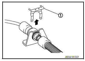
- Remove the lock plate (1).
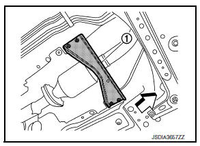
- Remove the tunnel stay (1).
 : Front
- Remove the exhaust front tube and sub muffler from the exhaust system. Refer to EX-5, "Removal and Installation".
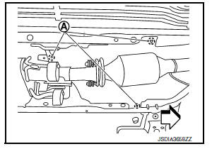
- Remove the heat plate fixtures (A).
 : Front
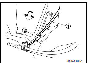
- Remove the control cable (1) from the bracket (2).
 : Front
- Remove the control cable from the vehicle.
INSTALLATION
Installation is in the reverse order of removal.
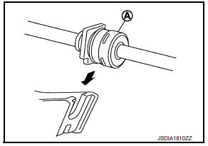
- From below the vehicle, press the grommet (A) into place until the pawls (B) make a click sound.
CAUTION:
- Place the grommet on the floor, then fasten it in place from below the vehicle.
- Check that pulling down on the grommet does not disconnect it.
- Pay attention to the following when connecting the control cable to the shift selector.
- When connecting the control cable (1) to the shift selector assembly (2), face the grooved surface of the rib (A) up and insert the control cable until it stops.
- Install the socket (A) onto the shift selector.
CAUTION:
- Place the socket onto the shift selector, then fasten it in place from above.
- Check that the pulling on the socket does not disconnect it.
Inspection and Adjustment
INSPECTION AND ADJUSTMENT
Check the CVT position. If a malfunction is found, adjust the CVT position. Refer to TM-150, "Inspection" (Inspection) or TM-150, "Adjustment" (Adjustment).
 CVT Shift selector
Exploded View
Shift selector knob
Lock pin
Knob cover
Position indication panel
Detent switch
Shift lock unit
Park position switch
Shift selector assembly
Shift selector harne ...
 Key interlock cable
Exploded View
Shift selector assembly
Clip
Key interlock cable
Clip
Key cylinder
Removal and Installation
REMOVAL
CAUTION:
Always apply the parking brake before performing remov ...
Other materials:
P1226 TP Sensor
DTC Logic
DTC DETECTION LOGIC
DTC No.
CONSULT screen terms
(Trouble diagnosis content)
DTC detecting condition
Possible cause
P1226
CTP LEARNING-B1
(CTP LEARNING-B1)
Closed throttle position learning is not performed
successfully, repeatedly.
Electric thr ...
Basic inspection
Diagnosis and repair workflow
Work flow
OVERALL SEQUENCE
DETAILED FLOW
1.GET INFORMATION FOR SYMPTOM
Get detailed information from the customer about the symptom (the condition
and the environment when the
incident/malfunction occurred).
>> GO TO 2
2.CONFIRM THE SYMPTOM
Try to ...
Ipdm-e branch line circuit
Diagnosis procedure
1.Check connector
Turn the ignition switch OFF.
Disconnect the battery cable from the negative terminal.
Check the terminals and connectors of the IPDM E/R for damage, bend and
loose connection (unit side
and connector side).
Is the inspection result normal?
Yes ...
