Nissan Sentra Service Manual: Connector symbols
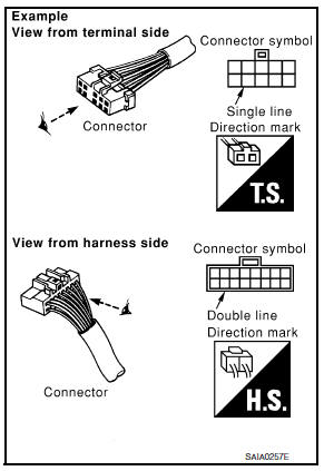
Most of connector symbols in wiring diagrams are shown from the terminal side.
- Connector symbols shown from the terminal side are enclosed by a single line and followed by the direction mark.
- Connector symbols shown from the harness side are enclosed by a double line and followed by the direction mark.
- Certain systems and components, especially those related to
OBD, may use a new style slide-locking type harness connector.
For description and how to disconnect, refer to PG section, –≤–Ç—öDescription–≤–Ç—ú, –≤–Ç—öHARNESS CONNECTOR–≤–Ç—ú.
- Male and female terminals
Connector guides for male terminals are shown in black and female terminals in white in wiring diagrams.

 Sample/wiring diagram -example-
For detail, refer to following GI-11, "Description".
...
Other materials:
Diagnosis system [abs actuator and electric unit (control
unit)]
CONSULT Function (ABS)
FUNCTION
CONSULT can display each diagnostic item using the following
direct diagnostic modes.
Direct Diagnostic Mode
Description
ECU identification
The ABS actuator and electric unit (control unit) part number is
displayed.
Self Diagnos ...
P0139 HO2S2
DTC Logic
DTC DETECTION LOGIC
The heated oxygen sensor 2 has a much longer switching time
between rich and lean than the air fuel ratio (A/F) sensor 1. The oxygen
storage capacity of the three way catalyst 1 causes the longer
switching time. To judge the malfunctions of heated oxygen sensor
2, ...
Diagnosis system (ECM)
Diagnosis description : 1st trip detection
logic and two trip detection logic
When a malfunction is detected for the first time, 1st trip DTC and 1st trip
Freeze Frame data are stored in the
ECM memory. The MIL will not illuminate at this stage. <1st trip>
If the same malfunction is dete ...
