Nissan Sentra Service Manual: Condenser
Exploded view
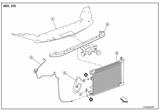
- Core support upper cover
- High-pressure pipe
- High-pressure flexible hose
- Refrigerant pressure sensor
- Condenser and liquid tank assembly
- Core support upper
 Front
Front
Condenser
Condenser : removal and installation
REMOVAL
- Discharge the refrigerant. Refer to HA-23, "Recycle Refrigerant".
- Reposition the hood lock assembly. Refer to DLK-154, "HOOD LOCK CONTROL : Exploded View".
NOTE:
Disconnection of the hood release cable is not necessary.
- Remove the core support upper. Refer to HA-39, "Exploded View".
- Remove the front grille. Refer to EXT-23, "Removal and Installation".
- Disconnect the harness connector from the refrigerant pressure sensor.
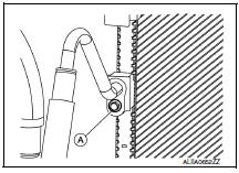
- Remove the bolt (A) that retains the high-pressure flexible hose to the condenser, then disconnect the high-pressure flexible hose from the condenser and liquid tank assembly.
CAUTION:
Cap or wrap the joint of the hose with suitable material such as vinyl tape to avoid the entry of air.
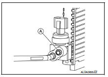
- Remove the bolt (A) that retains the high-pressure pipe to the condenser, then disconnect the high-pressure pipe from the condenser and liquid tank assembly.
- Remove the condenser and liquid tank assembly.
INSTALLATION
Installation is in the reverse order of removal.
CAUTION:
- Do not reuse O-rings.
- Apply A/C oil to the O-rings of the condenser for installation.
- After charging refrigerant, check for leaks. Refer to HA-21, "Leak Test".
Refrigerant pressure sensor
Refrigerant pressure sensor : removal and installation
REMOVAL
- Discharge the refrigerant. Refer to HA-23, "Recycle Refrigerant".
- Reposition the hood lock assembly. Refer to DLK-154, "HOOD LOCK CONTROL : Exploded View".
NOTE:
Disconnection of the hood release cable is not necessary.
- Remove the core support upper. Refer to HA-39, "Exploded View".
- Disconnect the harness connector from the refrigerant pressure sensor.
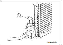
- Remove the refrigerant pressure sensor (1) from the liquid tank on the condenser.
CAUTION:
Do not damage the condenser fins.
INSTALLATION
Installation is in the reverse order of removal.
CAUTION:
- Do not reuse the O-ring.
- Apply A/C compressor oil to the new O-ring for installation.
- After charging refrigerant, check for leaks. Refer to HA-21, "Leak Test".
 Cooler pipe and hose
Exploded view
High-pressure service port
High-pressure pipe
Expansion valve
Low-pressure service port
Low-pressure flexible hose
Compressor
Refrigerant pressure sensor
Condenser ...
 Heating and cooling unit assembly
Exploded view
With air conditioning
Defroster seal
Center ventilator seal
Upper distribution module
Side ventilator seal (LH)
Blower motor
Blower unit
Intake door motor
Power tr ...
Other materials:
Rear regulator
Exploded View
Rear door panel
Rear door glass regulator motor
Rear door glass regulator
Rear door glass
Rear door glass rubber run
Removal and Installation
NOTE:
RH rear door panel shown; LH side similar
REMOVAL
Remove the rear door finisher. Refer to INT-19, "Removal ...
Clutch piping
Exploded View
CSC (Concentric Slave Cylinder)
Clip
Clutch tube
Clutch damper
Bracket
Clutch master cylinder
Hydraulic Layout
Clutch tube
Lock pin
CSC (Concentric Slave Cylinder)
Clutch damper
Clutch master cylinder
Clutch pedal
Removal and Installation
CAU ...
Precaution
Precaution for supplemental restraint system (srs) "air bag" and "seat
belt pre-tensioner"
The supplemental restraint system such as “air bag” and “seat belt pre-tensioner”,
used along
with a front seat belt, helps to reduce the risk or severity of injur ...
