Nissan Sentra Service Manual: Component parts
Component Parts Location
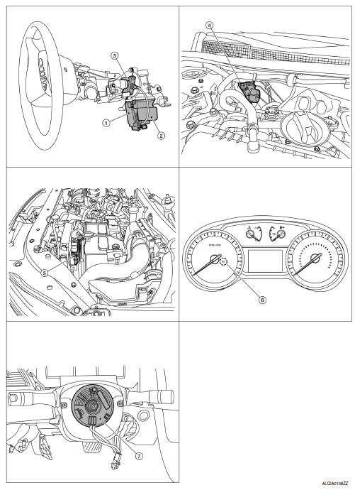
-
EPS control unit (view with steering column removed from vehicle)
-
EPS motor (view with steering column removed from vehicle)
-
Torque sensor (view with steering column removed from vehicle)
-
ABS actuator and electric unit (control unit)
-
ECM
-
EPS warning lamp (In combination meter)
-
Steering angle sensor (view with steering wheel removed)
Component Description
| Components parts | Reference |
| EPS control unit | STC-6, "EPS Control Unit" |
| EPS motor | STC-6, "EPS Motor, Torque Sensor, Reduction Gear" |
| Torque sensor | STC-6, "EPS Motor, Torque Sensor, Reduction Gear" |
| Reduction gear | STC-6, "EPS Motor, Torque Sensor, Reduction Gear" |
| EPS warning lamp | STC-9, "WARNING/INDICATOR/CHIME LIST : Warning Lamp/ Indicator Lamp" |
| ECM | Transmits mainly the following signals to EPS control unit via
CAN communication.
|
| ABS actuator and electric unit (control unit) | Transmits mainly the following signal to EPS control unit via
CAN communication.
|
| Combination meter | Transmits mainly the following signal to EPS control unit via
CAN communication.
Turns ON the EPS warning lamp according to the signal from EPS control unit via CAN communication. |
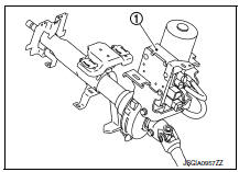
EPS Control Unit
-
EPS control unit (1) is installed to steering column assembly.
-
EPS control unit performs an arithmetical operation on data, such as steering wheel turning force (sensor signal) from the torque sensor, vehicle speed signal, etc. Then it generates an optimum assist torque signal to the EPS motor according to the driving condition.
-
EPS control unit decreases the output signal to EPS motor while extremely using the power steering function (e.g., full steering) consecutively for protecting EPS motor and EPS control unit (Overload protection control).
EPS Motor, Torque Sensor, Reduction Gear
EPS motor (1), torque sensor (2) and reduction gear (3) are installed to steering column assembly.
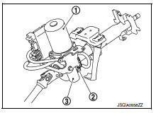
EPS MOTOR
EPS motor provides the assist torque by the control signal from EPS control unit.
TORQUE SENSOR
Torque sensor detects the steering torque, and transmits the signal to EPS control unit.
REDUCTION GEAR
Reduction gear increases the assist torque provided from EPS motor with worm gears, and outputs to the column shaft.

 System
EPS system
EPS SYSTEM : System Description
SYSTEM DIAGRAM
DESCRIPTION
EPS control unit performs an arithmetical operation on data,
such
as steering wheel turning force (sensor signal ...
Other materials:
Wiring diagram
Intelligent key system/engine start function
Wiring diagram
Nissan vehicle immobilizer systemnats
Wiring Diagram
Vehicle security system
Wiring diagram
...
Ipdm-e branch line circuit
Diagnosis procedure
1.Check connector
Turn the ignition switch OFF.
Disconnect the battery cable from the negative terminal.
Check the terminals and connectors of the IPDM E/R for damage, bend and
loose connection (unit side
and connector side).
Is the inspection result normal?
Yes ...
P0130 A/F Sensor 1
DTC Logic
DTC DETECTION LOGIC
To judge the malfunction, the diagnosis checks that the A/F signal computed
by ECM from the A/F sensor 1
signal fluctuates according to fuel feedback control.
DTC No.
CONSULT screen terms
(Trouble diagnosis content)
DTC detecting condition
Possi ...
