Nissan Sentra Service Manual: Component parts
STARTING SYSTEM (WITH INTELLIGENT KEY)
Component Parts Location
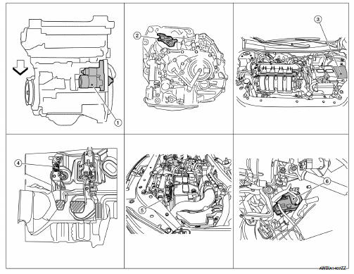
- Starter motor
- Transmission range switch (CVT Models)
- IPDM E/R (view with air inlet duct removed)
- Clutch interlock switch (M/T Models)
- ECM
- BCM (view under instrument panel, left side of vehicle)
Component Description
| Component part | Description |
| Starter motor | The starter motor plunger closes and the motor is supplied with battery power, which in turn cranks the engine, when the S terminal is supplied with electric power. |
| Transmission range switch (CVT Models) | Transmission range switch supplies power to the starter relay and starter control relay inside the IPDM E/R when the shift selector is placed in the P or N position. |
| IPDM E/R | CPU inside IPDM E/R operates the starter relay when the ignition switch is in the start position. |
| Clutch interlock switch (M/T Models) | Clutch interlock switch supplies power to the coil side of the starter when the clutch pedal is depressed to crank the engine. |
| ECM | ECM controls the starter control relay inside the IPDM E/R. |
| BCM | BCM controls the starter relay inside IPDM E/R. |

 System
STARTING SYSTEM (WITH INTELLIGENT KEY)
Component Parts Location
Starter motor
Transmission range switch (CVT Models)
IPDM E/R (view with air inlet duct
removed)
Clutch interlock switc ...
Other materials:
Replacing
Replace the wiper blades if they are worn.
To replace the windshield wiper blades, follow
the procedure below:
When ignition switch is ON or within
60 seconds after placing the ignition switch
from ON to OFF position.
Quickly push the windshield wiper and
washer lever to the mist pos ...
Fuel injector and fuel tube
Exploded View
Bracket
Fuel tube bracket
Fuel feed tube
Quick connector cap
Fuel tube
O-ring (black)
Fuel injector
O-ring (green)
Injector clip
CAUTION:
Do not remove or disassemble parts unless instructed.
Removal and Installation
WARNING:
Put a ą▓ąéčÜCAUTION: FLAM ...
Engine compartment check locations
MRA8DE engine
Engine oil filler cap
Brake and clutch (if so equipped) fluid
reservoir
Air cleaner
Battery
Fuse/fusible link box
Engine coolant reservoir
Radiator cap
Engine oil dipstick
Drive belt location
Windshield-washer fluid reservoir
...
