Nissan Sentra Service Manual: Component parts
Component parts location
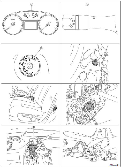
- Combination meter
- Combination switch (lighting and turn signal switch)
- Key switch (without intelligent key system)
- Push-button ignition switch (with intelligent key system)
- Seat belt buckle switch lh
- Front door switch lh
- Bcm (view with instrument panel removed)
- ABS actuator and electric unit (control unit)
- Parking brake switch (view with center console removed)
Component description
| Unit | Description |
| Combination meter |
|
| Lighting switch | Transmits lighting switch status signal to the bcm. |
| BCM | Transmits signals provided by various units to the combination meter with can communication line. |
| Front door switch lh | Transmits door switch signal to bcm. |
| Key switch | Transmits key switch signal to bcm. |
| Push-button ignition switch | Provides ignition switch status to the bcm |
| Seat belt buckle switch LH | Transmits seat belt buckle switch lh signal to the combination meter. |
| Parking brake switch | Transmits parking brake switch signal to the combination meter. |
| Abs actuator and electric unit (control unit) | Transmits the vehicle speed signal to combination meter with can communication line. |

 System
Warning chime system
Warning chime system : system diagram
Warning chime system : system description
Description
The buzzer for warning chime system is installed in the combination
meter.
...
Other materials:
M&A branch line circuit
Diagnosis procedure
1.Check connector
Turn the ignition switch off.
Disconnect the battery cable from the negative terminal.
Check the terminals and connectors of the combination meter for damage,
bend and loose connection
(unit side and connector side).
Is the inspection result nor ...
Front disc brake
BRAKE PAD
BRAKE PAD : Inspection
PAD WEAR
Check brake pad thickness from an inspection hole on caliper body.
Check using a scale if necessary
Wear limit thickness : Refer to BR-55, "Front Disc
Brake".
DISC ROTOR
DISC ROTOR : Inspection
APPEARANCE
Check surface of disc rotor ...
Front wiper auto stop signal circuit
Component function check
1. Check front wiper (auto stop) operation
Consult data monitor
Select “WIP AUTO STOP” of IPDM E/R DATA MONITOR item.
Operate the front wiper.
With the front wiper operation, check the monitor status.
Is the inspection result normal?
YES >> ...
