Nissan Sentra Service Manual: Component parts
Component parts location
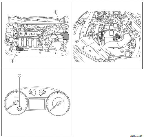
- Generator
- IPDM E/R (view with air inlet duct removed)
- ECM
- Battery current sensor
- Charge warning lamp indicator
Component description
| Component part | Description |
| Generator (IC regulator) | The IC regulator controls the power generation voltage
by the target
power generation voltage based on the received PWM command
signal.
When there is no PWM command signal, the generator performs the normal power generation according to the characteristic of the IC regulator. |
| IPDM E/R | The IPDM E/R converts the received power generation command value into a pulse width modulated (PWM) command signal and sends it to the IC regulator. |
| ECM | The battery current sensor detects the charging/discharging current
of the battery. The ECM judges the battery condition based on
this signal.
The ECM judges whether to request more output via the power generation voltage variable control according to the battery condition. When performing the power generation voltage variable control, the ECM calculates the target power generation voltage according to the battery condition and sends the calculated value as the power generation command value to the IPDM E/R. |
| Battery current sensor | The battery current sensor is located on the negative battery cable terminal. The battery current sensor detects the charging/discharging current of the battery and sends a voltage signal to the ECM according to the current value detected. |
| Combination meter (charge warning lamp) | The IC regulator warning function activates to illuminate the
charge warning lamp if any of the following symptoms occur while
generator is operating:
В·Excessive voltage is produced.
В·No voltage is produced. |

 Charging system
System Diagram
System Description
The generator provides DC voltage to operate the vehicle's electrical system
and to keep the battery charged.
The voltage output is controlled by the IC ...
Other materials:
Automatic door locks
All doors lock automatically when the vehicle
speed reaches 15 MPH (24 km/h).
All doors unlock automatically when the ignition
is placed in the OFF position (models
with Intelligent Key system) or when the key
is removed from the ignition switch (models
without Intelligent Key system) ...
P060B ECM
DTC Logic
DTC DETECTION LOGIC
DTC No.
CONSULT screen terms
(Trouble diagnosis content)
DTC detecting condition
Possible cause
P060B
CONTROL MODULE
(Internal control module A/
D processing performance)
ECM internal analog/digital conversion processing
syst ...
P2096, P2097 A/F Sensor 1
DTC Logic
DTC DETECTION LOGIC
DTC No.
CONSULT screen terms
(Trouble diagnosis content)
DTC detecting condition
Possible Cause
P2096
POST CAT FUEL TRIM SYS B1
(Post catalyst fuel trim system
too lean bank 1)
The output voltage computed by ECM from the
A/F ...
