Nissan Sentra Service Manual: Component parts
Component Parts Location
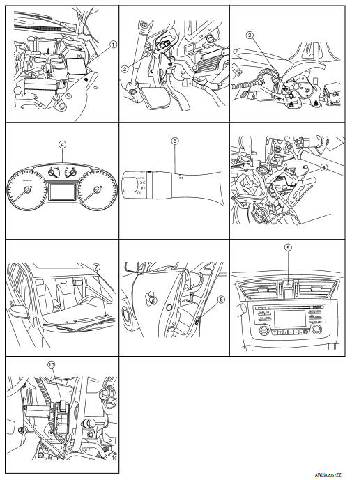
- IPDM E/R, (Headlamp high relay, Headlamp low relay, Taillamp relay and Front fog lamp relay (if equipped))
- Stop lamp switch
- Parking brake switch
- Combination meter
- Combination switch (lighting and turn signal switch)
- BCM (view with combination meter removed)
- Optical sensor
- Front door switch LH (Other doors similar)
- Hazard switch
- Daytime light relay (if equipped)
Component Description
| Part | Description |
| BCM | Controls the exterior lighting system. |
| Combination switch (Lighting & turn signal switch) | Refer to BCS-9, "COMBINATION SWITCH READING SYSTEM : System Description" (with Intelligent Key system) or BCS-80, "COMBINATION SWITCH READING SYSTEM : System Description" (without Intelligent Key system). |
| IPDM E/R | Controls the integrated relays and supplies voltage to the load according to the request from the BCM via CAN communication. |
| Stop lamp switch | Transmits power when the brake pedal is pressed to operate stop lamps. |
| Combination meter | Refer to MWI-8, "METER SYSTEM : System Description". |
| Daytime light relay (if equipped) | Sends power to the daytime lamp when operated by the IPDM E/R. |
| Front door switch LH/RH | Transmits the door open signal to the BCM. |
| Rear door switch LH/RH | |
| Optical sensor | Optical sensor converts the outside brightness (lux) to voltage and transmits the optical sensor signal to BCM to operate the autolight system. |
| Parking brake switch | Transmits the parking brake switch signal to the combination meter to operate the autolight system. |
| Hazard switch | Inputs the hazard switch signal to BCM. |

 System
Headlamp system
HEADLAMP SYSTEM : System Diagram
HEADLAMP SYSTEM : System Description
LOW BEAM OPERATION
When the lighting switch is in 2nd position, the BCM receives input
requesting the h ...
Other materials:
Work Flow
STEP
DESCRIPTION
STEP 1
Get detailed information about the conditions and the
environment when the incident occurred.
The following are key pieces of information required to make a good
analysis:
WHAT
Vehicle Model, Engine, Transmission/Transaxle and ...
P1551, P1552 Battery current sensor
DTC Logic
DTC DETECTION LOGIC
DTC No.
CONSULT screen terms
(Trouble diagnosis content)
DTC detecting condition
Possible cause
P1551
BAT CURRENT SENSOR
(Battery current sensor)
An excessively low voltage from the sensor
is sent to ECM.
Harness or ...
System
EPS system
EPS SYSTEM : System Description
SYSTEM DIAGRAM
DESCRIPTION
EPS control unit performs an arithmetical operation on data,
such
as steering wheel turning force (sensor signal) from the torque
sensor, vehicle speed signal, etc. Then it generates an optimum
assist torque ...
