Nissan Sentra Service Manual: Clutch pedal
Exploded View
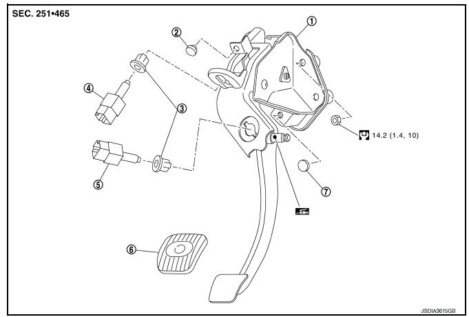
- Clutch pedal
- Stopper rubber
- Clip
- Clutch interlock switch (if equipped)
- Clutch pedal position switch (if equipped)
- Pedal pad
- Pedal stopper rubber
Removal and Installation
REMOVAL
- Remove instrument lower panel LH. Refer to IP-21, "Removal and Installation".
- Disconnect the harness connector from the clutch pedal position switch (if equipped).
- Disconnect the harness connector from the clutch interlock switch (if equipped).
- Disconnect clip of harness from clutch pedal.
- Remove clutch master cylinder rod end from clutch pedal.
- Remove clutch pedal position switch and clip from clutch pedal (if equipped).
- Remove clutch interlock switch and clip from clutch pedal (if equipped).
- Remove clutch pedal from the vehicle
- Remove pedal pad from clutch pedal.
- Remove stopper rubber and pedal stopper rubber from clutch pedal, using a suitable remover.
INSTALLATION
Installation is in the reverse order of removal.
CAUTION:
After applying recommended grease, press clutch master cylinder rod end into clutch pedal until it stops.
Inspection and Adjustment
INSPECTION AFTER REMOVAL
- Check clutch pedal for bend, damage, or a cracked weld. If bend, damage, or a cracked weld is found, replace clutch pedal.
- Check pedal stopper rubber (if equipped). If damage or deformation is
found, replace pedal stopper rubber.
(if equipped)
- Check stopper rubber. If damage or deformation is found, replace stopper rubber.
- Check pedal pad. If wear or damage is found, replace pedal pad.
INSPECTION AFTER INSTALLATION
- Check the height of clutch pedal. Refer to CL-5, "Inspection and Adjustment".
- Check the clutch interlock switch position (if equipped). Refer to CL-5, "Inspection and Adjustment".
- Check the clutch pedal position switch position (if equipped). Refer to CL-5, "Inspection and Adjustment".
ADJUSTMENT AFTER INSTALLATION
- Adjust the clutch interlock switch position (if equipped). Refer to CL-5, "Inspection and Adjustment".
- Adjust the clutch pedal position switch position (if equipped). Refer to CL-5, "Inspection and Adjustment".

 Clutch master cylinder
Exploded View
Reservoir hose
Reservoir tank
Clutch master cylinder
Removal and Installation
REMOVAL
CAUTION:
Keep painted surface on the body or other parts free of clutch
flui ...
Other materials:
Rear-facing child restraint installation using LATCH
Refer to all Warnings and Cautions in the “Child
safety” and “Child restraints” sections before installing
a child restraint.
NISSAN does not recommend the use of the
lower anchors if the combined weight of the child
and the child restraint exceeds 65 lbs (29.5 kg). If
the combined w ...
Precaution
Precautions for Trouble Diagnosis
Caution:
Follow the instructions listed below. Failure to do this may cause
damage to parts:
Never apply 7.0 V or more to the measurement terminal.
Use a tester with open terminal voltage of 7.0 V or less.
Turn the ignition switch off and disconnect the ...
Precaution
Precaution for Supplemental Restraint System (SRS) "AIR BAG" and "SEAT
BELT PRE-TENSIONER"
The Supplemental Restraint System such as –≤–Ç—öAIR BAG–≤–Ç—ú and –≤–Ç—öSEAT BELT PRE-TENSIONER–≤–Ç—ú,
used along
with a front seat belt, helps to reduce the risk or severity of injur ...
