Nissan Sentra Service Manual: Charging system preliminary inspection
Diagnosis Procedure
1.CHECK BATTERY TERMINALS CONNECTION
Check if battery terminals are clean and tight.
Is the inspection result normal? YES >> GO TO 2.
NO >> Repair battery terminal connection. Confirm repair by performing complete Charging system test using EXP-800 NI or GR8-1200 NI (if available). Refer to the applicable Instruction Manual for proper testing procedures.
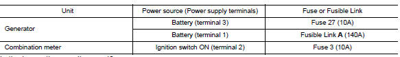
2.Check fuse
Check for blown fuse and fusible link.
Is the inspection result normal? Yes >> go to 3.
No >> replace the blown fuse or fusible link after repairing the affected circuit.
3.Check generator ground terminal connection
Check if connector f17 terminal 5 and 6 is clean.
Is the inspection result normal? Yes >> go to 4.
No >> repair connection.
4.Check drive belt tension
Check drive belt tension. Refer to chg-29, "removal and installation".
Is the inspection result normal? Yes >> inspection end.
No >> repair as needed.

 Power generation voltage variable control system operation inspection
Diagnosis Procedure
Regarding wiring diagram information. Refer to chg-9, "wiring diagram".
Caution:
When performing this inspection, always use a charged battery that has
completed the ...
Other materials:
Vanity mirror lamp
Removal and installation
Caution:
Do not attempt to separate the vanity mirror lamp from the sun visor or
damage to the components
may occur.
Note:
The vanity mirror lamp is replaced as part of the sun visor. Refer to
int-40, "removal and installation".
Bulb or lens replacement
...
Front door
Door assembly
Door assembly : removal and installation
CAUTION:
Use two people when removing or installing the front door assembly
due to its heavy weight.
When removing and installing front door assembly, support front
door using a suitable tool.
Do not use air tools or electric to ...
Bcm branch line circuit
Diagnosis procedure
1.Check connector
Turn the ignition switch off.
Disconnect the battery cable from the negative terminal.
Check the terminals and connectors of the BCM for damage, bend and loose
connection (unit side and
connector side).
Is the inspection result normal?
YES > ...
