Nissan Sentra Service Manual: Center console assembly
Exploded View
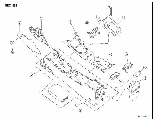
- Center console upper finisher
- Center console side finisher (RH)
- Center console side finisher (LH)
- Center console side finisher screw cover (LH/ RH)
- Center console assembly
- Center console screw cover (LH/ RH)
- Center console rear finisher
- Center console rear finisher cover
- Center console coin tray (if equipped)
- Heated seat switch finisher (if equipped)
- Center console cup holder finisher
- Shift selector finisher
- Storage bin
Removal and Installation
REMOVAL
- Remove the center console side finishers (1) (LH/RH).
- Remove the center console side finisher screw (A) (LH/RH).
- Release the clips using a suitable tool, then remove the center console side finisher.
 Metal clip
- Remove the shift selector finisher (1).
- Remove cluster lid C lower. Refer to IP-20, "Removal and Installation - Cluster Lid C Lower".
- Remove the shift selector screws (A).
- Release the clips using a suitable tool, then remove the shift selector finisher.
 Metal clip
- Release the center console cup holder finisher clips, then remove the center console cup holder finisher (1).
 Metal clip
- Remove the center console screw cover (1) using a suitable tool and the center console screws (A) (LH/RH).
- Remove the remaining center console screws (A).
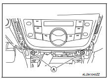
- Disconnect the harness connectors from the center console assembly and remove.
INSTALLATION
Installation is in the reverse order of removal.
 Steering column covers
Removal and Installation
REMOVAL
Remove the steering column cover screws (A), then remove the
steering column upper (1) and lower (2) covers.
NOTE:
Shown with steering wheel removed for ...
 Cluster lid A
Removal and Installation
REMOVAL
Release cluster lid A clips and pawls using a suitable tool.
: Pawl
Metal clip
Remove cluster lid A.
INSTALLATION
Installation is in the reverse ...
Other materials:
Changing engine coolant
A NISSAN dealer can change the engine coolant.
The service procedure can be found in the
NISSAN Service Manual.
Improper servicing can result in reduced
heater performance and engine overheating.
WARNING
To avoid the danger of being scalded,
never change the coolant when the ...
Power outlet
Center Console
Console Box (if so equipped)
The power outlets are for powering electrical
accessories such as cellular telephones. They
are rated at 12 volt, 120W (10A) maximum.
The power outlets are powered only when the
ignition switch is in the ACC or ON position.
CAUTION
The ...
Automatic speed control device (ASCD)
AUTOMATIC SPEED CONTROL DEVICE (ASCD) : System Description
SYSTEM DIAGRAM
BASIC ASCD SYSTEM
Refer to Owner's Manual for ASCD operating instructions.
Automatic Speed Control Device (ASCD) allows a driver to keep vehicle at
predetermined constant speed
without depressing accelerator pedal ...
