Nissan Sentra Service Manual: Can communication circuit
Diagnosis procedure
1.CONNECTOR INSPECTION
- Turn the ignition switch OFF.
- Disconnect the battery cable from the negative terminal.
- Disconnect all the unit connectors on CAN communication system.
- Check terminals and connectors for damage, bend and loose connection.
Is the inspection result normal? YES >> GO TO 2.
NO >> Repair the terminal and connector.
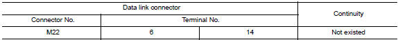
2.CHeck harness continuity (short circuit)
Check the continuity between the data link connector terminals.
Is the inspection result normal? Yes >> go to 3.
No >> check the harness and repair the root cause.
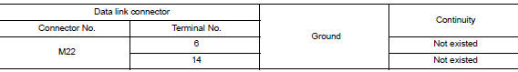
3.Check harness continuity (short circuit)
Check the continuity between the data link connector and the ground.
Is the inspection result normal? Yes >> go to 4.
No >> check the harness and repair the root cause.
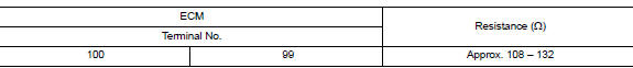
4.Check ecm and bcm termination circuit
- Remove the ecm and the bcm.
- Check the resistance between the ECM terminals.
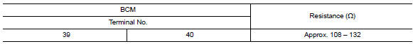
- Check the resistance between the bcm terminals.
Is the measurement value within the specification? Yes >> go to 5.
No >> replace the ecm and/or the bcm.
5.Check symptom
Connect all the connectors. Check if the symptoms described in the “symptom (results from interview with customer)” are reproduced.
Inspection result
Reproduced>>GO TO 6.
Non-reproduced>>Start the diagnosis again. Follow the trouble diagnosis procedure when past error is detected.
6.Check unit reproduction
- Perform the reproduction test as per the following procedure for each unit.
- Turn the ignition switch off.
- Disconnect the battery cable from the negative terminal.
- Disconnect one of the unit connectors of can communication system.
Note:
Ecm and bcm have a termination circuit. Check other units first.
- Connect the battery cable to the negative terminal. Check if the symptoms described in the “Symptom (Results from interview with customer)” are reproduced.
Note:
Although unit-related error symptoms occur, do not confuse them with other symptoms.
Inspection result
Reproduced>>connect the connector. Check other units as per the above procedure.
Non-reproduced>>replace the unit whose connector was disconnected.
 Bcm branch line circuit
Diagnosis procedure
1.Check connector
Turn the ignition switch off.
Disconnect the battery cable from the negative terminal.
Check the terminals and connectors of the bcm for damage, bend and ...
 Can system (type 2)
Dtc/circuit diagnosis ...
Other materials:
Tire chains
CAUTION
Tire chains/cables should not be installed
on P205/50R17 size tires. Installation of
the tire chains/cables on P205/50R17 size
tires will cause damage to the vehicle. If
you plan to use tire chains/cables, you
should install P205/55R16 size tires on
your vehicle.
Use of tire chains m ...
Precaution for Work
When removing or disassembling each component, be careful not to damage
or deform it. If a component
may be subject to interference, be sure to protect it with a shop cloth.
When removing (disengaging) components with a screwdriver or similar
tool, be sure to wrap the component
with a ...
P1715 Input speed sensor
Description
ECM receives input speed sensor signal from TCM through CAN communication
line. ECM uses this signal for
engine control.
DTC Logic
DTC DETECTION LOGIC
NOTE:
If DTC P1715 is displayed with DTC UXXXX, first perform the trouble
diagnosis for DTC UXXXX.
If DTC P1715 is displa ...
