Nissan Sentra Service Manual: Camshaft valve clearance
Inspection and Adjustment
INSPECTION
Perform inspection after removal, installation or replacement of camshaft or valve-related parts, or if there are unusual engine conditions regarding valve clearance.
- Remove rocker cover. Refer to EM-46, "Exploded View".
- Measure the valve clearance with the following procedure:
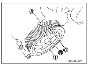
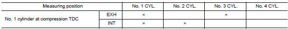
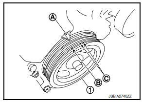
- Set No. 1 cylinder at TDC of its compression stroke.
- Rotate crankshaft pulley (1) clockwise and align TDC mark (no paint) (B) to timing indicator (A) on front cover.
(C) : White paint mark (Not used for service)
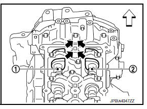
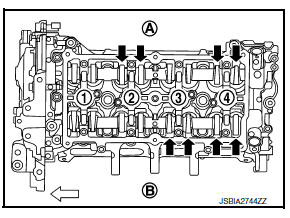
- At this time, check that both intake and exhaust cam lobes of
No. 1 cylinder face inside (
 )
)
as shown.
(1) : Camshaft (INT)
(2) : Camshaft (EXH)
 : Engine front
- If they do not face inside, rotate crankshaft pulley once more (360 degrees) and align as shown.
- Measure the clearance between valve lifter and camshaft using suitable tool as shown.
Valve clearance : Refer to EM-119, "Camshaft".
- Measure the valve clearances at locations marked “×” [locations
indicated with black arrow (
![)] as shown using suitable](images/books/349/2/index119.gif)
)] as shown using suitable tool.
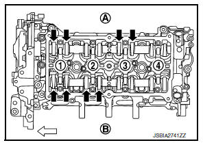
(A) : Exhaust side
(B) : Intake side
(1) : No. 1 cylinder
(2) : No. 2 cylinder
(3) : No. 3 cylinder
(4) : No. 4 cylinder
 Engine front
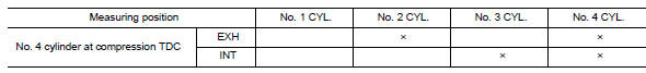
- Set No. 4 cylinder at TDC of its compression stroke.
- Rotate crankshaft pulley (1) one revolution (360 degrees) and align TDC mark (no paint) (B) to timing indicator (A) on front cover.
(C) : White paint mark (Not used for service)
- Measure the valve clearance at locations marked “×” [locations
indicated with black arrow (
 )]
)]
as shown using suitable tool.
(A) : Exhaust side
(B) : Intake side
(1) : No. 1 cylinder
(2) : No. 2 cylinder
(3) : No. 3 cylinder
(4) : No. 4 cylinder
 : Engine front
- If out of standard, perform adjustment. Refer to “ADJUSTMENT”.
ADJUSTMENT
- Perform adjustment depending on selected head thickness of valve lifter.
- Remove camshaft. Refer to EM-60, "Exploded View".
- Remove valve lifters at the locations that are out of the standard.
- Measure the center thickness of the removed valve lifters using suitable tool (A).
- Use the equation below to calculate valve lifter thickness for replacement.
Valve lifter thickness calculation: t = t1 + (C1 – C2)
t = Valve lifter thickness to be replaced
t1 = Removed valve lifter thickness
C1 = Measured valve clearance
C2 = Standard valve clearance:
-
Intake : 0.29 mm (0.011 in)
-
Exhaust : 0.32 mm (0.013 in)
- Thickness of new valve lifter (B) can be identified by stamp mark (A) on the reverse side (inside the cylinder).
- Stamp mark “302” indicates 3.02 mm (0.1189 in) in thickness.
NOTE:
Available thickness of valve lifter: 26 sizes range 3.00-3.50 mm (0.1181-0.1378 in) in steps of 0.02 mm (0.0008 in) (when manufactured at factory). Refer to EM-119, "Camshaft".
- Install the selected valve lifter.
- Install camshaft. Refer to EM-60, "Exploded View".
- Install timing chain and related parts. Refer to EM-48, "Exploded View".
- Manually rotate crankshaft pulley a few rotations.
- Check that the valve clearances are within the standard. Refer to “INSPECTION”.
- Installation of remaining components is in the reverse order of removal.
- Warm up the engine, and check for unusual noise and vibration.
 Air cleaner filter
Exploded View
Mass air flow sensor
Mass air flow gasket
Clamp
Air duct (suction side)
Resonator
Clamp
PCV hose
Clamp
Clamp
Air cleaner cover
Mounting rubber
Air cleaner f ...
 Compression pressure
Inspection
Warm up the engine to full operating temperature.
Release fuel pressure. Refer to EC-143, "Work Procedure".
Remove ignition coil and spark plug from each cylinder. Refer t ...
Other materials:
Manual transmission (if so equipped)
The ignition switch includes a device that helps
prevent accidental removal of the key while driving.
The key can only be removed when the ignition
switch is in the LOCK position.
On manual transmission models, to turn the ignition
key to LOCK position from ACC or ON
position, turn the ...
Air conditioning cut control
AIR CONDITIONING CUT CONTROL : System Description
SYSTEM DIAGRAM
INPUT/OUTPUT SIGNAL CHART
Sensor
Input Signal to ECM
ECM function
Actuator
Crankshaft position sensor (POS)
Engine speed*
Piston position
Air conditioner
cut control
IPDM E/R
↓Air ...
Precaution for work
When removing or disassembling each component, be careful not to damage
or deform it. If a component
may be subject to interference, be sure to protect it with a shop cloth.
When removing (disengaging) components with a screwdriver or similar
tool, be sure to wrap the component
with a ...
