Nissan Sentra Service Manual: C1708, C1709, C1710, C1711 Transmitter (no data)
DTC Logic
NOTE:
The Signal Tech II Tool (J-50190) can be used to perform the following functions. Refer to the Signal Tech II User Guide for additional information.
- Activate and display TPMS transmitter IDs
- Display tire pressure reported by the TPMS transmitter
- Read TPMS DTCs
- Register TPMS transmitter IDs
DTC DETECTION LOGIC
| DTC | Display Item | Malfunction detected condition | Possible causes |
| C1708 | [NO DATA] FL | Tire pressure data signal from the front LH wheel transmitter cannot be detected. |
|
| C1709 | [NO DATA] FR | Tire pressure data signal from the front RH wheel transmitter cannot be detected. | |
| C1710 | [NO DATA] RR | Tire pressure data signal from the rear RH wheel transmitter cannot be detected. | |
| C1711 | [NO DATA] RL | Tire pressure data signal from the rear LH wheel transmitter cannot be detected. |
DTC CONFIRMATION PROCEDURE
1.PERFORM SELF DIAGNOSTIC RESULT
 With CONSULT
- Drive for 3 minutes at a speed of 40 km/h (25 MPH) or more, then drive normally for 10 minutes.
- Stop the vehicle.
- Perform “SELF DIAGNOSTIC RESULT”.
Is DTC “C1708”, “C1709”, “C1710” or “C1711” detected? YES >> Proceed to WT-27, "Diagnosis Procedure".
NO >> Inspection End.
Diagnosis Procedure
NOTE:
The Signal Tech II Tool (J-50190) can be used to perform the following functions. Refer to the Signal Tech II User Guide for additional information.
- Activate and display TPMS transmitter IDs
- Display tire pressure reported by the TPMS transmitter
- Read TPMS DTCs
- Register TPMS transmitter IDs
Regarding Wiring Diagram information, refer to WT-15, "WITH INTELLIGENT KEY : Wiring Diagram" or WT- 18, "WITHOUT INTELLIGENT KEY : Wiring Diagram".
1.CHECK DATA MONITOR
 With CONSULT
- Drive for 3 minutes at a speed of 40 km/h (25 MPH) or more, then drive normally for 10 minutes.
- Stop the vehicle.
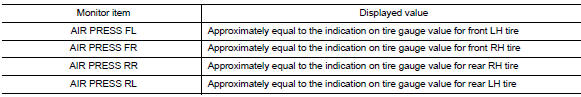
- On “DATA MONITOR” select “AIR PRESS FL”, “AIR PRESS FR”, “AIR PRESS RR” and “AIR PRESS RL”.
- Within 5 minutes after vehicle is stopped, read the values displayed on CONSULT
Are all tire pressures displayed 0 kPa (psi)? YES >> GO TO 2.
NO >> GO TO 5.
2.CHECK REMOTE KEYLESS ENTRY RECEIVER POWER CIRCUIT
Check voltage between remote keyless entry receiver connector and ground.
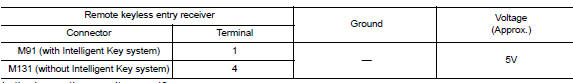
Is the inspection result normal?
YES >> GO TO 3.
NO >> Repair or replace harness or connectors.
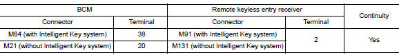
3.Check remote keyless entry receiver signal circuit
- Turn the ignition switch OFF.
- Disconnect BCM and remote keyless entry receiver connectors.
- Check continuity between BCM and remote keyless entry receiver connectors.
- Check continuity between BCM connector and ground.
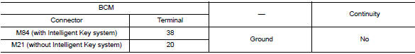
Is the inspection result normal? YES >> GO TO 4.
NO >> Repair or replace the malfunctioning harness or connector.
4.Check remote keyless entry receiver ground circuit
Check continuity between BCM and remote keyless entry receiver connectors.
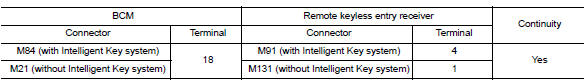
Is the inspection result normal? YES >> GO TO 5.
NO >> Repair or replace the malfunctioning harness or connector.
5.Transmitter id registration
Perform transmitter ID registration. Refer to WT-22, "Work Procedure".
Can the tire pressure sensor ID registration be completed? YES >> GO TO 6.
NO >> Replace applicable transmitter. Refer to WT-50, "Removal and Installation".
6.Check tire pressure signal
 With CONSULT
- Drive for 3 minutes at a speed of 40 km/h (25 MPH) or more, then drive normally for 10 minutes.
- Stop the vehicle.
- On “DATA MONITOR” select “AIR PRESS FL”, “AIR PRESS FR”, “AIR PRESS RR” and “AIR PRESS RL”.
- Within 5 minutes after vehicle stopped, check that the tire pressures are within specification. Refer to WT- 54, "Tire Air Pressure".
Is the inspection result normal? YES >> Inspection End.
NO >> Replace the BCM. Refer to BCS-73, "Removal and Installation" (with Intelligent Key system) or BCS-126, "Removal and Installation" (without Intelligent Key system).
 C1704, C1705, C1706, C1707 Low tire pressure
DTC Logic
NOTE:
The Signal Tech II Tool (J-50190) can be used to perform the following
functions. Refer to the Signal Tech II
User Guide for additional information.
Activate and display TPMS ...
 C1716, C1717, C1718, C1719 Transmitter (pressure data)
DTC Logic
NOTE:
The Signal Tech II Tool (J-50190) can be used to perform the following
functions. Refer to the Signal Tech II
User Guide for additional information.
Activate and display TPMS ...
Other materials:
Voice commands
You can use voice commands to operate various
Bluetooth® Hands-Free Phone System features
using the NISSAN Voice Recognition system. For
more details, see “NISSAN Voice Recognition
System” in this section.
Voice Prompt Interrupt
While using the voice recognition system, the
system voice ...
NISSAN Voice Recognition System (if so
equipped)
The NISSAN Voice Recognition system allows
hands-free operation of the systems equipped on
this vehicle, such as the phone and navigation
systems.
To operate NISSAN Voice Recognition, press
the button located on the steering
wheel.
When prompted, speak the command for the
system you wi ...
Washing
Wash dirt off with a wet sponge and plenty of
water. Clean the vehicle thoroughly using a mild
soap, a special vehicle soap or general purpose
dishwashing liquid mixed with clean, lukewarm
(never hot) water.
CAUTION
Do not use car washes that use acid in
the detergent. Some car washes, es ...
