Nissan Sentra Service Manual: C1604 Torque sensor
DTC Logic
DTC DETECTION LOGIC
| DTC | Display item | Malfunction detected condition | Possible cause |
| C1604 | TORQUE SENSOR | When torque sensor output signal is malfunctioning |
|
DTC CONFIRMATION PROCEDURE
1.PRECONDITIONING
If DTC CONFIRMATION PROCEDURE has been previously conducted, always turn ignition switch OFF and wait at least 10 seconds before conducting the next test.
>> GO TO 2.
2.DTC REPRODUCTION PROCEDURE
 With CONSULT
-
Turn the ignition switch OFF to ON.
-
Perform EPS self-diagnosis.
Is DTC “C1604” detected? YES >> Proceed to diagnosis procedure. Refer to STC-25, "Diagnosis Procedure".
NO >> Inspection End.
Diagnosis Procedure
Regarding Wiring Diagram information, refer to STC-15, "Wiring Diagram".
1.Check torque sensor power supply circuit
-
Turn ignition switch ON.
-
Check voltage between EPS control unit harness connector terminals and ground.
CAUTION:
Steering wheel is neutral position. (There is no steering force.)
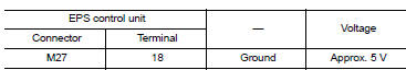
Is the inspection result normal? YES >> GO TO 2.
NO >> Perform the trouble diagnosis for battery power supply circuit. Refer to STC-22, "Diagnosis Procedure".
2.Check torque sensor ground circuit
-
Turn ignition switch OFF.
-
Check continuity between eps control unit harness connector terminal and ground.
Caution:
Steering wheel is neutral position. (There is no steering force.)
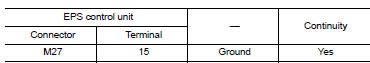
Is the inspection result normal? Yes >> go to 3.
No >> repair open circuit or short to ground or short to power in harness or connectors.
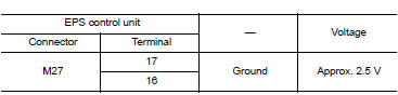
3.Check torque sensor signal
-
Turn ignition switch off to on.
-
Check voltage between eps control unit harness connector terminal and ground.
Caution:
Steering wheel is neutral position. (There is no steering force.)
-
Start the engine.
-
Check voltage between EPS control unit harness connector terminal and ground.
CAUTION:
Steering wheel is right or left turn.
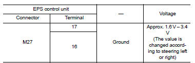
Is the inspection result normal? Yes >> go to 4.
No >> torque sensor is malfunction. Replace steering column assembly. Refer to st-12, "removal and installation".
4.Check connector
-
Turn ignition switch off.
-
Disconnect eps control unit harness connector.
-
Check terminal for deformation, disconnection, looseness, and so on. If any malfunction is found, repair or replace terminal.
Is the inspection result normal? Yes >> replace eps control unit. Refer to stc-39, "removal and installation".
No >> repair or replace the malfunctioning parts.
 C1601 Battery power supply
DTC Logic
DTC DETECTION LOGIC
DTC
Display item
Malfunction detected condition
Possible cause
C1601
BATTERY VOLT
When a power supply voltage to the EPS control unit
...
 C1606 EPS Motor
DTC Logic
DTC DETECTION LOGIC
Dtc
Display item
Malfunction detected condition
Possible cause
C1606
EPS MOTOR
When the motor driver malfunction of EPS control
unit o ...
Other materials:
Combination meter
Reference Value
VALUES ON THE DIAGNOSIS TOOL
NOTE:
The following table includes information (items) inapplicable to this
vehicle. For information (items) applicable
to this vehicle, refer to CONSULT display items.
Note:
Some items are not available according to vehicle specificat ...
P0846 Transmission fluid pressure SEN/SW B
DTC Logic
DTC DETECTION LOGIC
DTC
CONSULT screen terms
(Trouble diagnosis content)
DTC detection condition
Possible causes
P0846
TRANSMISSION FLUID
PRESSURE SEN/SW B
(Transmission Fluid Pressure
Sensor/Switch B Circuit
Range/Performance)
The detection ...
Main line between dlc and av circuit
Diagnosis procedure
1.Check harness continuity (open circuit)
Turn the ignition switch off.
Disconnect the battery cable from the negative terminal.
Disconnect the following harness connectors.
ECM
AV control unit
Check the continuity between the data link connector and the av ...
