Nissan Sentra Service Manual: C1601 Battery power supply
DTC Logic
DTC DETECTION LOGIC
| DTC | Display item | Malfunction detected condition | Possible cause |
| C1601 | BATTERY VOLT | When a power supply voltage to the EPS control unit is maintained at 17.5 V or more or at less than 9 V continuously for five second or more. |
|
DTC CONFIRMATION PROCEDURE
1.PRECONDITIONING
If DTC CONFIRMATION PROCEDURE has been previously conducted, always turn ignition switch OFF and wait at least 10 seconds before conducting the next test.
>> GO TO 2.
2.DTC REPRODUCTION PROCEDURE
 With CONSULT
-
Turn the ignition switch OFF to ON.
-
Perform EPS self-diagnosis.
Is DTC C1601 detected? YES >> Proceed to diagnosis procedure. Refer to STC-22, "Diagnosis Procedure".
NO >> Inspection End.
Diagnosis Procedure
Regarding Wiring Diagram information, refer to STC-15, "Wiring Diagram".
1.Check EPS Control unit ground circuit
-
Turn ignition switch OFF.
-
Disconnect EPS control unit harness connector.
-
Check continuity between EPS control unit harness connector terminal and ground.
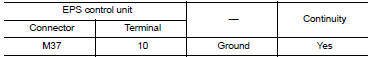
-
Connect EPS control unit harness connector.
Is the inspection result normal? YES >> GO TO 2.
NO >> Repair open circuit or short to ground or short to power in harness or connectors.
2.Check EPS Control unit power supply circuit (1)
-
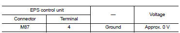
Check voltage between EPS control unit harness connector terminals and ground.
Is the inspection result normal? YES >> GO TO 4.
NO >> GO TO 3.
3.Check EPS Control unit power supply circuit
(2)
-
Turn ignition switch OFF.
-
Check the 10A fuse (#5).
-
Check the harness for open or short between EPS control unit harness connector terminal 4 and the 10A fuse (#5).
Is the inspection result normal? YES >> Perform the trouble diagnosis for ignition power supply circuit. Refer to PCS-70, "Wiring Diagram".
NO >> Repair or replace the malfunctioning parts.
4.Check EPS Control unit power supply circuit (3)
-
Turn ignition switch OFF.
-
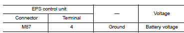
Check voltage between EPS control unit harness connector terminals and ground.
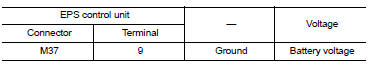
-
Turn ignition switch ON.
CAUTION:
Never start the engine.
-
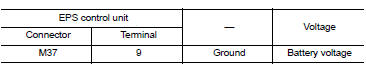
Check voltage between EPS control unit harness connector and ground.
Is the inspection result normal? YES >> GO TO 6.
NO >> GO TO 5.
5.CHECK EPS CONTROL UNIT POWER SUPPLY CIRCUIT (4)
-
Turn ignition switch OFF.
-
Check the 60A fusible link (#M).
-
Check the harness for open or short between EPS control unit harness connector terminal 9 and the 60A fusible link (#M).
Is the inspection result normal? YES >> Perform the trouble diagnosis for power supply circuit. Refer to PCS-70, "Wiring Diagram".
NO >> Repair or replace the malfunctioning parts.
6.CHECK TERMINALS AND HARNESS CONNECTORS
Check the EPS control unit pin terminals for damage or loose connection with harness connector.
Is the inspection result normal? YES >> EPS control unit is malfunctioning. Replace steering column assembly. Refer to ST-12, "Removal and Installation".
NO >> Repair or replace the malfunctioning parts.

 C1604 Torque sensor
DTC Logic
DTC DETECTION LOGIC
DTC
Display item
Malfunction detected condition
Possible cause
C1604
TORQUE SENSOR
When torque sensor output signal is malfunctioning
...
Other materials:
Diagnosis system (TCM)
DIAGNOSIS DESCRIPTION
DIAGNOSIS DESCRIPTION : 1 Trip Detection Diagnosis and 2 Trip Detection
Diagnosis
NOTE:
“Start the engine and turn OFF the ignition switch after warm-up.” This is
defined as 1 trip.
TRIP DETECTION DIAGNOSIS
When initial malfunction is detected, TCM mem ...
Precaution
Precaution for Supplemental Restraint System (SRS) "AIR BAG" and "SEAT
BELT PRE-TENSIONER"
The supplemental restraint system such as “air bag” and “seat belt pre-tensioner”,
used along
with a front seat belt, helps to reduce the risk or severity of injur ...
C1121, C1123, C1125, C1127 ABS OUT Valve system
DTC Logic
DTC DETECTION LOGIC
DTC DETECTION LOGIC
Display Item
Malfunction detected condition
Possible causes
C1121
FR LH OUT ABS SOL
When a malfunction is detected in front LH ABS OUT
valve.
Harness or connector
ABS actuator and electric unit
...
