Nissan Sentra Service Manual: C1164, C1165, C1166, C1167 CV/SV System
DTC Logic
Dtc detection logic
| DTC | Display Item | Malfunction detected condition | Possible causes |
| C1164 | CV 1 | When a malfunction is detected in cut valve 1. |
|
| C1165 | CV 2 | When a malfunction is detected in cut valve 2. | |
| C1166 | SV 1 | When a malfunction is detected in suction valve 1. | |
| C1167 | SV 2 | When a malfunction is detected in suction valve 2. |
DTC CONFIRMATION PROCEDURE
1.CHECK SELF DIAGNOSTIC RESULT
 With CONSULT.
-
Turn ignition switch OFF to ON.
-
Perform self diagnostic result.
Is DTC C1164, C1165, C1166 or C1167 detected? YES >> Proceed to diagnosis procedure. Refer to BRC-85, "Diagnosis Procedure".
NO >> Inspection End.
Diagnosis Procedure
Regarding Wiring Diagram information, refer to BRC-44, "Wiring Diagram".
1.CONNECTOR INSPECTION
-
Turn ignition switch OFF.
-
Disconnect ABS actuator and electric unit (control unit) connector.
-
Check connector and terminals for deformation, disconnection, looseness or damage.
Is the inspection result normal? YES >> GO TO 2.
NO >> Repair or replace as necessary.
2.Check abs actuator and electric unit (control unit) battery power supply
Check voltage between ABS actuator and electric unit (control unit) connector E33 terminal 25 and ground.
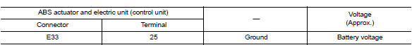
Is the inspection result normal? Yes >> go to 3.
No >> repair or replace malfunctioning components.
3.Check abs actuator and electric unit (control unit) ground circuit
Check continuity between abs actuator and electric unit (control unit) connector e33 terminals 13, 38 and ground.
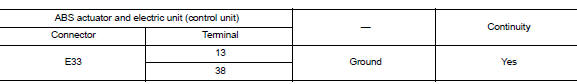
Is the inspection result normal? Yes >> replace abs actuator and electric unit (control unit). Refer to brc-110, "removal and installation".
No >> repair or replace malfunctioning components.
 C1155 BR Fluid level low
DTC Logic
Dtc detection logic
Dtc
Display item
Malfunction detected condition
Possible cause
C1155
C1155 br fluid level low
Brake fluid level is low or communication l ...
 U1000 CAN Comm circuit
DTC Logic
DTC DETECTION LOGIC
DTC
Display Item
Malfunction detected condition
Possible causes
U1000
CAN COMM CIRCUIT
When CAN communication signal is not continuously
...
Other materials:
For safe driving
For safe driving, adjust the seat and mirror to an appropriate
position before driving.
Correct driving posture
Adjust the angle of the seatback
so that you are sitting
straight up and so that you do
not have to lean forward to
steer.
Adjust the seat so that you can
depress the ped ...
Parking brake control
Exploded View
Parking brake lever assembly
Adjusting nut
Parking brake switch
Front parking brake cable
Rear parking brake cable (LH)
Rear parking brake cable (RH)
Front
Removal and Installation
REMOVAL
Parking Brake Control
Remove rear wheels and t ...
System
Headlamp system
HEADLAMP SYSTEM : System Diagram
HEADLAMP SYSTEM : System Description
LOW BEAM OPERATION
When the lighting switch is in 2nd position, the BCM receives input
requesting the headlamps to illuminate.
This input is communicated to the IPDM E/R across the CAN communication l ...
