Nissan Sentra Service Manual: C1121, C1123, C1125, C1127 ABS OUT Valve system
DTC Logic
DTC DETECTION LOGIC
| DTC DETECTION LOGIC | Display Item | Malfunction detected condition | Possible causes |
| C1121 | FR LH OUT ABS SOL | When a malfunction is detected in front LH ABS OUT valve. |
|
| C1123 | FR RH OUT ABS SOL | When a malfunction is detected in front RH ABS OUT valve. | |
| C1125 | RR LH OUT ABS SOL | When a malfunction is detected in rear LH ABS OUT valve. | |
| C1127 | RR RH OUT ABS SOL | When a malfunction is detected in rear RH ABS OUT valve. |
DTC CONFIRMATION PROCEDURE
1.CHECK SELF DIAGNOSTIC RESULT
 With CONSULT
-
Turn ignition switch ON.
-
Perform self diagnostic result.
Is DTC C1121, C1123, C1125 or C1127 detected? YES >> Proceed to diagnosis procedure. Refer to BRC-74, "Diagnosis Procedure".
NO >> Inspection End.
Diagnosis Procedure
Regarding Wiring Diagram information, refer to BRC-44, "Wiring Diagram".
1.CONNECTOR INSPECTION
-
Turn ignition switch OFF.
-
Disconnect ABS actuator and electric unit (control unit) connector.
-
Check connector and terminals for deformation, disconnection, looseness or damage.
Is the inspection result normal? YES >> GO TO 2.
NO >> Repair or replace as necessary.
2.Check ABS Actuator and electric unit (control unit) battery power supply
Check voltage between ABS actuator and electric unit (control unit) connector E33 terminal 25 and ground.
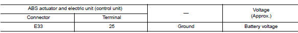
Is the inspection result normal? YES >> GO TO 3.
NO >> Repair or replace malfunctioning components.
3.Check abs actuator and electric unit (control unit) ground circuit
Check continuity between ABS actuator and electric unit (control unit) connector E33 terminals 13, 38 and ground.
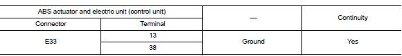
Is the inspection result normal? YES >> Replace ABS actuator and electric unit (control unit). Refer to BRC-110, "Removal and Installation".
NO >> Repair or replace malfunctioning components.
 C1120, C1122, C1124, C1126 ABS In valve system
DTC Logic
Dtc detection logic
DTC
Display Item
Malfunction detected condition
Possible causes
C1120
FR LH IN ABS SOL
When a malfunction is detected in front LH ABS IN
...
 C1130 Engine signal
DTC Logic
DTC DETECTION LOGIC
DTC
Display Item
Malfunction detected condition
Possible causes
C1130
ENGINE SIGNAL 1
When a malfunction is detected in ECM system.
...
Other materials:
Precaution
Precaution for supplemental restraint system (srs) "air bag" and "seat
belt pre-tensioner"
The supplemental restraint system such as “air bag” and “seat belt pre-tensioner”,
used along
with a front seat belt, helps to reduce the risk or severity of injur ...
Engine maintenance
Drive belt
Drive belt : inspection
Alternator
Drive belt auto-tensioner
Crankshaft pulley
A/c compressor
Water pump
Drive belt
Possible use range
New drive belt range
Ndicator
Warning:
Perform this step when engine is stopped.
Check that the indicator of drive bel ...
Brakes
If the brakes do not operate properly, have the
brakes checked by a NISSAN dealer.
Self-adjusting brakes
Your vehicle is equipped with self-adjusting
brakes.
The front (and rear– if so equipped) disc-type
brakes self-adjust every time the brake pedal is
applied. The rear drum-type brakes ...
