Nissan Sentra Service Manual: C1116 Stop lamp switch
DTC Logic
DTC DETECTION LOGIC
| DTC | Display item | Malfunction detected condition | Possible cause |
| C1116 | STOP LAMP SW | When stop lamp switch circuit is open. |
|
DTC CONFIRMATION PROCEDURE
1.Check self-diagnosis results
Check the self-diagnosis results.
Is above displayed on the self-diagnosis display? Yes >> proceed to diagnosis procedure. Refer to brc-70, "diagnosis procedure".
No >> inspection end.
Diagnosis Procedure
Regarding wiring diagram information, refer to brc-44, "wiring diagram".
1.Connector inspection
-
Disconnect stop lamp switch connector and abs actuator and electric unit (control unit) connector.
-
Check terminals for deformation, disconnection, looseness or damage.
Is the inspection result normal? Yes >> go to 2
No >> repair or replace as necessary.
2.Check stop lamp switch circuit
-
Connect stop lamp switch connector.
-
Check voltage between abs actuator and electric unit (control unit) connector e33 terminal 30 and ground.
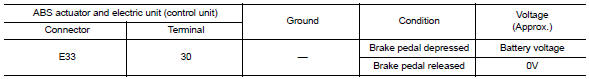
Is the inspection result normal? Yes >> replace abs actuator and electric unit (control unit). Refer to brc-110, "removal and installation".
No >> go to 3
3.Check stop lamp switch circuit for open
-
Disconnect stop lamp switch connector.
-
Check continuity between abs actuator and electric unit (control unit) connector e33 terminal 30 and stop lamp switch connector e60 terminal 2.
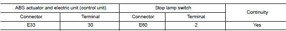
Is the inspection result normal? Yes >> go to 4.
No >> repair or replace as necessary.
4.Check stop lamp switch circuit for short
Check continuity between abs actuator and electric unit (control unit) connector e33 terminal 30 and ground.
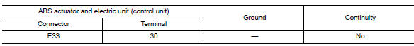
Is the inspection result normal? Yes >> replace stop lamp switch. Refer to br-22, "exploded view" no >> repair harness or connectors.
 C1115 ABS Sensor [abnormal signal]
DTC Logic
DTC DETECTION LOGIC
DTC
Display Item
Malfunction detected condition
Possible causes
C1115
ABS SENSOR
[ABNORMAL SIGNAL]
When difference in wheel speed betw ...
 C1120, C1122, C1124, C1126 ABS In valve system
DTC Logic
Dtc detection logic
DTC
Display Item
Malfunction detected condition
Possible causes
C1120
FR LH IN ABS SOL
When a malfunction is detected in front LH ABS IN
...
Other materials:
Precaution for supplemental restraint system (srs) "air bag" and "seat belt
pre-tensioner"
The Supplemental Restraint System such as “AIR BAG” and “SEAT BELT PRE-TENSIONER”,
used along
with a front seat belt, helps to reduce the risk or severity of injury to the
driver and front passenger for certain
types of collision. Information necessary to service the system ...
System description
Component parts
Component parts location
Instrument lower finisher
Component description
Sport mode switch
The sport mode switch is installed to the instrument lower finisher.
When the sport mode indicator lamp on the combination meter
is off and the sport mode switch is pres ...
System description
DESCRIPTION
Engine Cooling System Schematic
CVT Models
Radiator
Water inlet
Reservoir tank
Thermostat
Engine oil cooler
Thermostat housing
Water pump
Cylinder head
Cylinder block
Water control valve
Water outlet
Heater
Electric throttle control actuator
CVT oil wa ...
