Nissan Sentra Service Manual: C1101, C1102, C1103, C1104 Wheel sensor
Description
When the sensor rotor rotates, the magnetic field changes. It converts the magnetic field changes to current signals (rectangular wave) and transmits them to the ABS actuator and electric unit (control unit).
DTC Logic
DTC DETECTION LOGIC
| DTC | Display Item | Malfunction detected condition | Possible causes |
| C1101 | RR RH SENSOR-1 |
|
|
| C1102 | RR LH SENSOR-1 |
|
|
| C1103 | FR RH SENSOR-1 |
|
|
| C1104 | FR LH SENSOR-1 |
|
DTC CONFIRMATION PROCEDURE
1.CHECK SELF DIAGNOSTIC RESULT
 With CONSULT.
-
Start engine and drive vehicle at approximately 21 km/h (13 MPH) or more for approximately 5 minutes.
-
Perform self diagnostic result.
Is DTC C1101, C1102, C1103 or C1104 detected? YES >> Proceed to diagnosis procedure. Refer to BRC-56, "Diagnosis Procedure".
NO >> Inspection End.
Diagnosis Procedure
Regarding Wiring Diagram information, refer to BRC-44, "Wiring Diagram".
CAUTION:
Do not check between wheel sensor terminals.
1.CONFIRM DTC
 With CONSULT
-
Perform self-diagnostic result of ABS and record all active DTCs.
-
Clear all DTCs.
-
Perform DTC confirmation procedure. Refer to BRC-56, "DTC Logic".
Does DTC C1101, C1102, C1103 or C1104 reset? YES >> GO TO 2.
NO >> Refer to GI-39, "Intermittent Incident".
2.INSPECT WHEEL SENSOR
Inspect the suspect wheel sensor for damage or deformation.
Is the inspection result normal? YES >> GO TO 3.
NO >> Repair or replace as necessary.
3.HARNESS AND CONNECTOR INSPECTION
-
Disconnect ABS actuator and electric unit (control unit) connector E33 and wheel sensor connector of suspect wheel.
-
Check harness, connectors and terminals for corrosion, deformation, disconnection, looseness or damage.
Is the inspection result normal? YES >> GO TO 4.
NO >> Repair or replace as necessary.
4.CHECK WHEEL SENSOR OUTPUT SIGNAL
-
Connect ABS active wheel sensor tester (J-45741) to wheel sensor using appropriate adapter.
-
Turn on the ABS active wheel sensor tester power switch.
NOTE:
The green POWER indicator should illuminate. If the POWER indicator does not illuminate, replace the battery in the ABS active wheel sensor tester before proceeding.
-
Spin the wheel of the vehicle by hand and observe the red SENSOR indicator on the ABS active wheel sensor tester. The red SENSOR indicator should flash on and off to indicate an output signal.
NOTE:
If the red SENSOR indicator illuminates but does not flash, reverse the polarity of the tester leads and retest.
Does the ABS active wheel sensor tester detect a signal? YES >> GO TO 5.
NO >> Replace the wheel sensor. Refer to BRC-106, "FRONT WHEEL SENSOR : Removal and Installation" or BRC-107, "REAR WHEEL SENSOR : Removal and Installation" .
5.Check wiring harness for short to voltage
-
Turn ignition switch ON.
-
Check voltage between wheel sensor harness connector terminals of suspect wheel and ground.
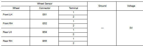
Is the inspection result normal? YES >> GO TO 6.
NO >> Repair the circuit.
6.Check wiring harness for short to ground
-
Turn ignition switch OFF.
-
Check continuity between wheel sensor harness connector terminals of suspect wheel and ground.

Is the inspection result normal? YES >> GO TO 7.
NO >> Repair the circuit.
7.Check wiring harness for short between circuits
Check continuity between wheel sensor harness connector terminals of suspect wheel.
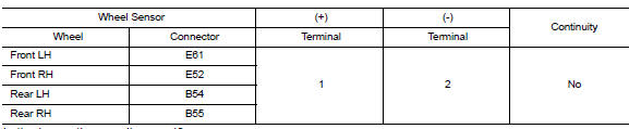
Is the inspection result normal? YES >> GO TO 8.
NO >> Repair the circuit.
8.Check wiring harness for open circuit
Check continuity between ABS actuator and electric unit (control unit) connector E33 and wheel sensor connector of wheel with DTC.
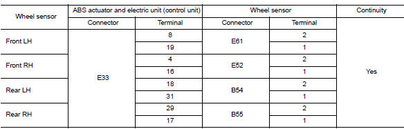
Is the inspection result normal? YES >> GO TO 9.
NO >> Repair the circuit.
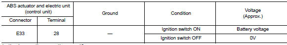
9.Check abs actuator and electric unit (control unit) power supply circuit
-
Turn ignition switch ON.
-
Check voltage between ABS actuator and electric unit (control unit) harness connector E33 terminal and ground.
Is the inspection result normal? YES >> GO TO 10.
NO >> Check the following:
-
10A fuse No. 50 located in the IPDM E/R
-
Harness between ABS actuator and electric unit (control unit) and IPDM E/R
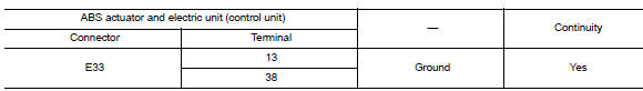
10.Check ABS Actuator and electric unit (control unit) ground circuit
-
Turn ignition switch OFF.
-
Check continuity between ABS actuator and electric unit (control unit) connector E33 terminals and ground.
The inspection result normal? Yes >> go to 11.
No >> repair or replace malfunctioning components.
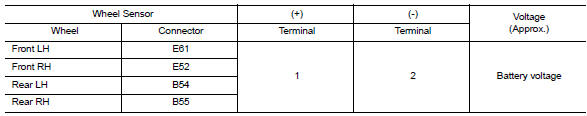
11.Check wheel sensor input voltage
-
Connect ABS actuator and electric unit (control unit) connector E33
-
Turn ignition switch ON.
-
Check voltage between suspect wheel sensor harness connector terminals.
Is the inspection result normal? YES >> Replace wheel sensor. Refer to BRC-106, "FRONT WHEEL SENSOR : Removal and Installation" or BRC-107, "REAR WHEEL SENSOR : Removal and Installation" . Then, GO TO 12.
NO >> Replace ABS actuator and electric unit (control unit). Refer to BRC-110, "Removal and Installation".
12.CONFIRM REPAIR
 With CONSULT
-
Clear all DTCs.
-
Perform DTC confirmation procedure. Refer to BRC-56, "DTC Logic".
Does DTC C1101, C1102, C1103 or C1104 reset? YES >> Replace ABS actuator and electric unit (control unit). Refer to BRC-110, "Removal and Installation".
NO >> Inspection End.

 C1105, C1106, C1107, C1108 Wheel sensor
Description
When the sensor rotor rotates, the magnetic field changes. It
converts the magnetic field changes to current
signals (rectangular wave) and transmits them to the ABS actuator and elec ...
Other materials:
The oil pressure warning lamp does not turn off
Description
The oil pressure warning lamp remains illuminated while the engine is running
(normal oil pressure).
Diagnosis procedure
1.Check combination meter input signal
Start the engine and select METER/M&A on CONSULT.
Observe oil w/l data monitor and the operation of the oil pres ...
Air cleaner and air duct
Exploded View
Mass air flow sensor
Mass air flow gasket
Clamp
Air duct (suction side)
Resonator
Clamp
PCV hose
Clamp
Clamp
Air cleaner cover
Mounting rubber
Air cleaner filter
Air cleaner body
Air duct inlet (lower)
Air duct inlet (upper)
Mounting rubber
Brack ...
Regulatory Information
FCC Regulatory information
CAUTION: To maintain compliance with
FCC’s RF exposure guidelines, use only the
supplied antenna. Unauthorized antenna,
modification, or attachments could damage
the transmitter and may violate FCC regulations.
Operation is subject to the following two cond ...
