Nissan Sentra Service Manual: Brake pedal position switch
Component Function Check
1.CHECK BRAKE PEDAL POSITION SWITCH FUNCTION
 With CONSULT
- Turn ignition switch ON.
- Select “ENGINE” using CONSULT.
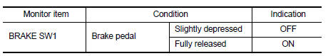
- Select “BRAKE SW1” in “DATA MONITOR” mode.
- Check “BRAKE SW1” indication under the following conditions.
 Without CONSULT
- Turn ignition switch ON.
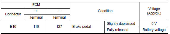
- Check the voltage between ECM harness connector terminals under the following conditions.
Is the inspection result normal? YES >> INSPECTION END
NO >> Proceed to EC-446, "Diagnosis Procedure".
Diagnosis Procedure
1.CHECK BRAKE PEDAL POSITION SWITCH POWER SUPPLY CIRCUIT
- Turn ignition switch OFF.
- Disconnect brake pedal position switch harness connector.
- Turn ignition switch ON.
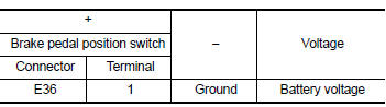
- Check the voltage between brake pedal position switch harness connector and ground.
Is the inspection result normal? YES >> GO TO 3.
NO >> GO TO 2.
2.CHECK STOP LAMP SWITCH POWER SUPPLY CIRCUIT
- Pull out #5 fuse.
- Check that the fuse is not fusing.
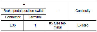
- Check the continuity between stop lamp switch harness connector and fuse terminal.
- Also check harness for short to ground and short to power.
Is the inspection result normal? YES >> Check power supply circuit for 12V battery power supply.
NO >> Repair or replace error-detected parts.
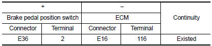
3.CHECK BRAKE PEDAL POSITION SWITCH INPUT SIGNAL CIRCUIT
- Turn ignition switch OFF.
- Disconnect ECM harness connector.
- Check the continuity between brake pedal position switch harness connector and ECM harness connector.
- Also check harness for short to ground and short to power.
Is the inspection result normal? YES >> GO TO 4.
NO >> Repair or replace error-detected parts.
4.CHECK BRAKE PEDAL POSITION SWITCH
Check brake pedal position switch. Refer to EC-447, "Component Inspection (Brake Pedal Position Switch)" Is the inspection result normal? YES >> Check intermittent incident. Refer to GI-39, "Intermittent Incident".
NO >> Replace brake pedal position switch. Refer to BR-22, "Exploded View".
Component Inspection (Brake Pedal Position Switch)
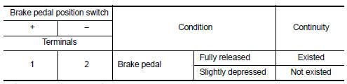
1.CHECK BRAKE PEDAL POSITION SWITCH-I
- Turn ignition switch OFF.
- Disconnect brake pedal position switch harness connector.
- Check the continuity between brake pedal position switch terminals under the following conditions.
Is the inspection result normal? YES >> INSPECTION END
NO >> GO TO 2.
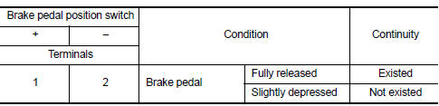
2.CHECK BRAKE PEDAL POSITION SWITCH-II
- Adjust brake pedal position switch installation. Refer to BR-15, "Adjustment".
- Check the continuity between brake pedal position switch terminals under the following conditions.
Is the inspection result normal? YES >> INSPECTION END
NO >> Replace brake pedal position switch. Refer to BR-22, "Exploded View".
 Sensor power supply 2 circuit
Description
ECM supplies a voltage of 5.0 V to some of the sensors systematically divided
into 2 groups, respectively.
Accordingly, when a short circuit develops in a sensor power source, a
ma ...
 ASCD Indicator
Component Function Check
1.CHECK ASCD INDICATOR FUNCTION
Check ASCD indicator under the following conditions.
ASCD INDICATOR
CONDITION
SPECIFICATION
CRUISE LAMP
Ig ...
Other materials:
P1551, P1552 Battery current sensor
DTC Logic
DTC DETECTION LOGIC
DTC No.
CONSULT screen terms
(Trouble diagnosis content)
DTC detecting condition
Possible cause
P1551
BAT CURRENT SENSOR
(Battery current sensor)
An excessively low voltage from the sensor
is sent to ECM.
Harness or ...
Maintenance data (fuel, oil level, etc.)
Dimensions and weights (2WD models)
*1: Unladen vehicles
*2: For LE or XLE grade models
*3: For SE or XSE grade models
*4: 205/65R16 tires
*5: 215/55R17 tires and TRD models with 235/40R19 tires
*6: 235/45R18, and SE or XSE grade models with 235/40R19 tires
*7: For TRD models
Dimensions an ...
Auto operation does not operate but manual operate normally (driver side)
Diagnosis Procedure
1.PERFORM INITIALIZATION PROCEDURE
Initialization procedure is executed and operation is confirmed.
Refer to PWC-29, "Work Procedure".
Is the inspection result normal?
YES >> INSPECTION END
NO >> GO TO 2.
2.CHECK ENCODER CIRCUIT
Check encoder cir ...
