Nissan Sentra Service Manual: Brake pedal
Exploded View
WITHOUT BRAKE PEDAL POSITION SWITCH
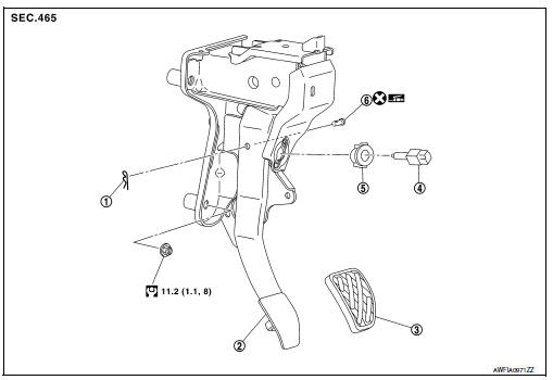
- Snap pin
- Brake pedal assembly
- Brake pedal pad
- Stop lamp switch
- Clip
- Clevis pin
 Apply multi-purpose grease.
WITH BRAKE PEDAL POSITION SWITCH
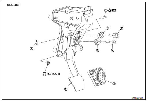
- Snap pin
- Brake pedal assembly
- Brake pedal pad
- Brake pedal position switch
- Clip
- Stop lamp switch
 Apply multi-purpose grease.
Removal and Installation
REMOVAL
- Remove instrument lower panel LH. Refer to IP-21, "Removal and Installation".
- Remove steering column lower cover. Refer to IP-16, "Removal and Installation".
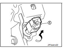
- Disconnect the harness connectors from the brake pedal position switch (if equipped) and the stop lamp switch.
- Rotate the stop lamp switch and the brake pedal position switch (if equipped) (1) counter clockwise to remove.
- Disconnect the accelerator pedal harness connector and harness clip.
- Remove snap pin and clevis pin from clevis on brake booster.
- Remove the brake pedal assembly.
CAUTION:
Secure the brake booster and brake master cylinder to avoid damage to components.
- Remove accelerator pedal from brake pedal assembly. Refer to ACC-3, "Removal and Installation".
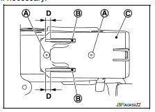
INSPECTION AFTER REMOVAL
Check for the following items and replace the brake pedal assembly, if necessary.
- Check the brake pedal upper rivet (A) for damage or wear.
- Check the brake pedal for bend, damage, and cracks on the welded parts.
- Check the lapping length (D) of sub-bracket (B) and slide plate (C).
Lapping length (D) : 6.5 mm (0.256 in) or more
INSTALLATION
Installation is in the reverse order of removal.
CAUTION:
- Do not reuse the clevis pin.
- Install the clevis pin in the proper direction. Refer to BR-22, "Exploded View".
- Apply multi-purpose grease to the clevis pin and the mating faces, if necessary.
ADJUSTMENT AFTER INSTALLATION
- Adjust each item of brake pedal after installing the brake pedal assembly to the vehicle. Refer to BR-15, "Adjustment".
- Perform the release position learning of the accelerator pedal. Refer to EC-138, "Work Procedure".

 Brake piping
FRONT
FRONT : Exploded View
Brake tube
ABS actuator and electric unit (control
unit)
Connector
Connector bracket
Master cylinder assembly
Brake booster
Lock plate
Brake hose
...
Other materials:
Rear drum brake
BRAKE LINING
BRAKE LINING : Inspection
INSPECTION
Brake Lining
Check brake lining wear thickness (A). Check using a scale if
necessary.
Lining wear thickness (A) : Refer to BR-55, "Rear
Drum Brake".
BRAKE DRUM
BRAKE DRUM : Inspection
INSPECTION
Appearance
Check surfac ...
B terminal circuit
Description
“B” terminal circuit supplies power to charge the battery and to operate the
vehicles electrical system.
Diagnosis procedure
Regarding wiring diagram information. Refer to chg-9, "wiring diagram".
1.Check “b” terminal connection
Turn ignition switc ...
Precaution for Supplemental Restraint System (SRS) "AIR BAG" and "SEAT
BELT PRE-TENSIONER"
The Supplemental Restraint System such as “AIR BAG” and “SEAT BELT PRE-TENSIONER”,
used along
with a front seat belt, helps to reduce the risk or severity of injury to the
driver and front passenger for certain
types of collision. Information necessary to service the system ...
