Nissan Sentra Service Manual: Brake pedal
Adjustment
BRAKE PEDAL HEIGHT
- Remove instrument lower panel LH. Refer to IP-21, "Removal and Installation".
- Disconnect the harness connectors from the brake pedal position switch (if equipped) and the stop lamp switch.
- Turn the stop lamp switch and brake pedal position switch (if equipped) 45В° counterclockwise.
- Loosen the input rod lock nut (1). Adjust the brake pedal height to the specification.
CAUTION:
- Check the height with the floor trim removed.
- The threaded end of the input rod (2) must project to the inner side (L) of the clevis (3).
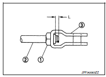
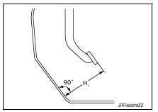
Brake pedal height (H1) : Refer to BR-54, "Brake Pedal".
- Tighten the input rod lock nut to specification. Refer to BR-34, "Exploded View".
- Check the brake pedal for smooth operation.
CAUTION:
The stop lamp must turn off when the brake pedal is released.
STOP LAMP SWITCH AND BRAKE PEDAL POSITION SWITCH
- Remove instrument lower panel LH. Refer to IP-21, "Removal and Installation".
- Disconnect the harness connectors from the brake pedal position switch (if equipped) and the stop lamp switch.
- Turn the stop lamp switch and brake pedal position switch (if equipped) 45В° counterclockwise.
- With the threaded ends of the stop lamp switch (2) and brake
pedal position switch (if equipped) (1) contacting the pedal
bracket (3), turn the switches 45В° clockwise to lock in place.
Check that both the stop lamp switch (2) and brake pedal position switch (if equipped) (1) contact ends to brake pedal bracket (3) clearance (A) are within specification.
- CAUTION:
- Make sure that the clearance (A) between the brake pedal bracket (3), stop lamp switch (2) and the brake pedal position switch (1) contact ends are within specification.
- The stop lamp must turn off when the brake pedal is released.
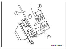
Clearance (A) : Refer to BR-54, "Brake Pedal".

 Brake fluid
Drain and Refill
CAUTION:
Do not spill or splash brake fluid on painted surfaces. Brake
fluid may damage paint. If brake fluid is
splashed on painted areas, wash it away with water immediate ...
Other materials:
Air fresheners
Most air fresheners use a solvent that could affect
the vehicle interior. If you use an air freshener,
take the following precautions:
Hanging-type air fresheners can cause permanent
discoloration when they contact vehicle
interior surfaces. Place the air freshener
in a location that all ...
Fuel injector and fuel tube
Exploded View
Bracket
Fuel tube bracket
Fuel feed tube
Quick connector cap
Fuel tube
O-ring (black)
Fuel injector
O-ring (green)
Injector clip
CAUTION:
Do not remove or disassemble parts unless instructed.
Removal and Installation
WARNING:
Put a “CAUTION: FLAM ...
Starting system (without intelligent key)
Wiring Diagram
...
