Nissan Sentra Service Manual: Brake pedal
Inspection
BRAKE PEDAL HEIGHT
Check the brake pedal height (H1) between the dash lower panel (1) and the brake pedal upper surface.
Brake pedal height (H1) : Refer to BR-54, "Brake Pedal".
CAUTION:
Check the brake pedal height with the floor trim removed.
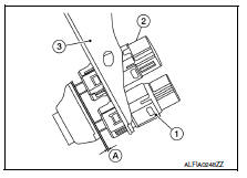
STOP LAMP SWITCH AND BRAKE PEDAL POSITION SWITCH
Check the clearance (A) between the switch assembly bracket (3), the stop lamp switch (2) and the brake pedal position switch (if equipped) (1).
Clearance (A) : Refer to BR-54, "Brake Pedal".
STOP LAMP SWITCH AND BRAKE PEDAL POSITION SWITCH
Check the clearance (A) between the switch assembly bracket (3), the stop lamp switch (2) and the brake pedal position switch (if equipped) (1).
Clearance (A) : Refer to BR-54, "Brake Pedal".
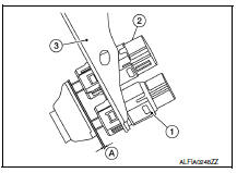
CAUTION:
The stop lamp must turn off when the brake pedal is released.
NOTE:
Pull the brake pedal pad to check that both the stop lamp switch (2) and brake pedal position switch (1) contact ends to brake pedal bracket (3) clearance (A) are within specification.
BRAKE PEDAL PLAY
Check that brake pedal play does not exist.
DEPRESSED BRAKE PEDAL HEIGHT
Check the brake pedal height (H2) between the dash lower panel (1) and the brake pedal upper surface when depressing the brake pedal at 490 N (50 kg, 110 lb) while turning engine ON.
Depressed brake pedal height (H2) : Refer to BR-54, "Brake Pedal".
CAUTION:
Check the depressed brake pedal height with the floor trim removed.
 Basic inspection
...
 Brake fluid
Inspection
BRAKE FLUID LEVEL
Make sure that the brake fluid level in the reservoir tank is between
the MAX and MIN lines.
Visually check around the reservoir tank for brake fluid leakage.
I ...
Other materials:
Camshaft valve clearance
Inspection and Adjustment
INSPECTION
Perform inspection after removal, installation or replacement of camshaft or
valve-related parts, or if there are
unusual engine conditions regarding valve clearance.
Remove rocker cover. Refer to EM-46, "Exploded View".
Measure the valve cle ...
Symptom diagnosis
CVT CONTROL SYSTEM
Symptom Table
The diagnosis item number indicates the order of check. Start checking in the
order from 1.
...
Component parts
Component parts location
Bcm (view with instrument panel removed)
Ipdm e/r (rear window defogger relay)
A/c auto amp. (View with a/c switch
assembly removed)
A/C switch assembly (rear window defogger
switch) (with auto A/C)
A/c switch assembly (rear window
defogger switch) (wit ...
