Nissan Sentra Service Manual: Basic inspection
Diagnosis and repair workflow
Work Flow (With GR8-1200 NI)
STARTING SYSTEM DIAGNOSIS WITH GR8-1200 NI
To test the starting system, use the following special service tool:
- GR8-1200 NI Multitasking battery and electrical diagnostic station
NOTE:
Refer to the diagnostic station Instruction Manual for proper starting system diagnosis procedures.
OVERALL SEQUENCE
DETAILED FLOW
NOTE:
To ensure a complete and thorough diagnosis, the battery, starter motor and generator test segments must be done as a set from start to finish.
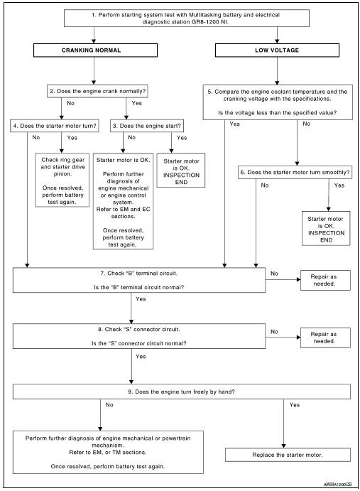
1.DIAGNOSIS WITH MULTITASKING BATTERY AND ELECTRICAL DIAGNOSTIC STATION GR8-1200 NI
Perform the starting system test with Multitasking battery and electrical diagnostic station GR8-1200 NI. For details and operating instructions, refer to diagnostic station Instruction Manual.
Test result
CRANKING NORMAL>>GO TO 2.
LOW VOLTAGE>>GO TO 5.
CHARGE BATTERY>>Perform the slow battery charging procedure. (Initial rate of charge is 10A for 12 hours.) Perform battery test again. Refer to diagnostic station instruction manual.
REPLACE BATTERY>>Before replacing battery, clean the battery cable clamps and battery posts. Perform battery test again. Refer to diagnostic station instruction manual. If second test result is “REPLACE BATTERY”, then do so. Perform battery test again to confirm repair.
2.CRANKING CHECK
Check that the starter motor operates properly.
Does the engine crank normally? YES >> GO TO 3.
NO >> GO TO 4.
3.ENGINE START CHECK
Check that the engine starts.
Does the engine start? YES >> Inspection End.
NO >> Perform further diagnosis of engine mechanical or engine control system. Refer to EM and EC sections. Once resolved, perform battery test again.
4.STARTER MOTOR ACTIVATION
Check that the starter motor operates.
Does the starter motor turn? YES >> Check ring gear and starter motor drive pinion. Once resolved, perform battery test again.
NO >> GO TO 7.
5.COMPARISON BETWEEN ENGINE COOLANT AND CRANKING VOLTAGE
Compare the engine coolant temperature and verify the cranking voltage is within specifications.
Minimum Specification of Cranking Voltage Referencing Coolant Temperature
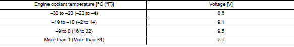
Is the voltage less than the specified value? YES >> GO TO 7.
NO >> GO TO 6.
6.STARTER OPERATION
Check the starter operation.
Does the starter motor turn smoothly? YES >> Inspection End.
NO >> GO TO 7.
7.“B” TERMINAL CIRCUIT INSPECTION
Check “B” terminal circuit. Refer to STR-26, "Diagnosis Procedure".
Is “B” terminal circuit normal? YES >> GO TO 8.
NO >> Repair as needed.
8.“S” CONNECTOR CIRCUIT INSPECTION
Check “S” connector circuit. Refer to STR-28, "Diagnosis Procedure".
Is “S” connector circuit normal? YES >> GO TO 9.
NO >> Repair as needed.
9.ENGINE ROTATION STATUS
Check that the engine can be rotated by hand.
Does the engine turn freely by hand? YES >> Replace starter motor.
NO >> Perform further diagnosis of engine mechanical or powertrain mechanism. Once resolved, perform battery test again using Multitasking battery and electrical diagnostic station GR8-1200 NI.
Refer to the diagnostic station Instruction Manual for proper testing procedures.
Work Flow (Without GR8-1200 NI)
 Starting system (without intelligent key)
Wiring Diagram
...

Other materials:
Daytime light system inoperative
Description
The daytime light system is inoperative even though the combination switch
(lighting and turn signal switch)
and parking brake switch are in the normal setting, also whenever engine is
operating.
Diagnosis procedure
1.Check daytime light operation
Perform bcm(headlamp) daytim ...
License plate lamp
Removal and Installation
REMOVAL
Remove the license lamp finisher. Refer to EXT-44, "Removal and
Installation".
Disconnect the harness connector (A) from the license plate
lamp (1).
Release pawl and remove.
: Pawl
INSTALLATION
Installation is in the reverse order of ...
Vehicle identification number (VIN) plate
The vehicle identification number (VIN) plate is
attached as shown. This number is the identification
for your vehicle and is used in the vehicle
registration.
Vehicle identification number (chassis number)
The vehicle identification number is located as
shown.
Engine serial number
...
