Nissan Sentra Service Manual: Basic inspection
Diagnosis and repair workflow
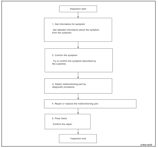
Work flow
Overall sequence

Detailed flow
1.Get information for symptom
Get detailed information from the customer about the symptom (the condition and the environment when the incident/malfunction occurred).
>> Go to 2
2.Confirm the symptom
Try to confirm the symptom described by the customer. Verify relation between the symptom and the condition when the symptom is detected.
>> GO TO 3
3.Detect malfunctioning part by diagnostic procedure
Inspect according to diagnostic procedure of the system.
Is malfunctioning part detected? YES >> GO TO 4
No >> go to 2
4.Repair or replace the malfunctioning part
- Repair or replace the malfunctioning part.
- Reconnect parts or connectors disconnected during diagnostic procedure.
>> GO TO 5
5.Final check
Refer to confirmed symptom in step 2, and make sure that the symptom is not detected.
Was the repair confirmed? Yes >> inspection end.
No >> go to 2
 Wiring diagram
Display audio with bose
Wiring diagram
...
 Dtc/circuit diagnosis
Power supply and ground circuit
Audio unit
Audio unit : diagnosis procedure
Regarding Wiring Diagram information, refer to AV-157, "Wiring Diagram".
1.Check fuse
Are the fuses blown?
...
Other materials:
Wiring diagram
Door mirror
Wiring diagram
Inside mirror
Wiring Diagram
...
Front door finisher
Exploded View
Front door panel
Front door finisher
Inside door handle escutcheon
Main power window and door lock/
unlock switch finisher
Door mirror corner finisher
Grommet
Clip
Pawl
Front
NOTE:
LH side shown; RH similar.
Removal and Installation
CAUTION:
When ...
Basic inspection
Inspection and adjustment
Additional service when replacing control unit (bcm)
Additional service when replacing control unit (bcm) : description
Before replacement
When replacing BCM, save or print current vehicle specification with CONSULT
configuration before replacement.
Note:
If “ ...
