Nissan Sentra Service Manual: Basic inspection
Diagnosis and repair workflow
Work Flow
OVERALL SEQUENCE
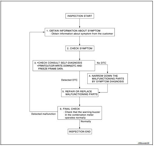
DETAILED FLOW
1.OBTAIN INFORMATION ABOUT SYMPTOM
Interview the customer to obtain as much information as possible about the conditions and environment under which the malfunction occurred.
>> GO TO 2.
2.CHECK SYMPTOM
- Check the symptom based on the information obtained from the customer.
- Check if any other malfunctions are present.
>> GO TO 3.
3.CHECK CONSULT SELF-DIAGNOSIS RESULTS
Connect CONSULT and perform self-diagnosis. Refer to MWI-26, "DTC Index".
Are self-diagnosis results normal? YES >> GO TO 4.
NO >> GO TO 5.
4.NARROW DOWN MALFUNCTIONING PARTS BY SYMPTOM DIAGNOSIS
Perform symptom diagnosis and narrow down the malfunctioning parts.
>> GO TO 5.
5.REPAIR OR REPLACE MALFUNCTIONING PARTS
Repair or replace malfunctioning parts.
NOTE:
If DTC is displayed, erase DTC after repairing or replacing malfunctioning parts.
>> GO TO 6.
6.FINAL CHECK
Check that the warning buzzer in the combination meter operates normally.
Does it operate normally? YES >> Inspection End.
NO >> GO TO 1.
 Wiring diagram
Warning chime system
Wiring diagram
...

Other materials:
Child safety rear door lock
Child safety locks help prevent the rear doors
from being opened accidentally, especially when
small children are in the vehicle.
The child safety lock levers are located on the
edge of the rear doors.
When the lever is in the unlock position 2 , the
door can be opened from the outside ...
Changing wheels and tires
Tire rotation
NISSAN recommends rotating the tires
every 7,500 miles (12,000 km).
See “Flat tire” in the “In case of emergency”
section of this manual for tire replacing
procedures.
As soon as possible, tighten the
wheel nuts to the specified torque
with a torque wrench.
Wheel ...
U1002 System comm (CAN)
DTC Logic
DTC DETECTION LOGIC
DTC
Display item
Malfunction detected condition
Possible cause
U1002
SYSTEM COMM(CAN)
When ABS actuator and electric unit (control unit) is not
transmitting or receiving CAN communication signal for 2
seconds or less.
C ...
