Nissan Sentra Service Manual: Basic inspection
Diagnosis and repair workflow
Work flow
Overall sequence
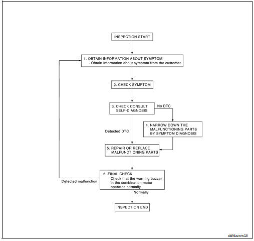
Detailed flow
1.Obtain information about symptom
Interview the customer to obtain as much information as possible about the conditions and environment under which the malfunction occurred.
>> GO TO 2.
2.Check symptom
- Check the symptom based on the information obtained from the customer.
- Check if any other malfunctions are present.
>> Go to 3.
3.Check consult self-diagnosis results
Connect consult and perform self-diagnosis. Refer to mwi-26, "dtc index".
Are self-diagnosis results normal? Yes >> go to 4.
No >> go to 5.
4.Narrow down malfunctioning parts by symptom diagnosis
Perform symptom diagnosis and narrow down the malfunctioning parts.
>> Go to 5.
5.Repair or replace malfunctioning parts
Repair or replace malfunctioning parts.
Note:
If dtc is displayed, erase dtc after repairing or replacing malfunctioning parts.
>> Go to 6.
6.Final check
Check that the warning buzzer in the combination meter operates normally.
Does it operate normally? Yes >> inspection end.
No >> go to 1.
 Wiring diagram
Meter system
Wiring diagram
Compass
Wiring diagram
...

Other materials:
Power supply and ground circuit
Diagnosis procedure
Regarding wiring diagram information, refer to bcs-51, "wiring diagram".
1.Check fuses and fusible link
Check that the following fuses and fusible link are not blown.
Is the fuse blown?
YES >> Replace the blown fuse or fusible link after repairing the aff ...
The light reminder warning does
not sound
Description
Light reminder warning chime does not sound even though headlamp is
illuminated.
Diagnosis procedure
1.Check combination meter input signal
Select the data monitor for the meter/m&a and check the buzzer monitor value.
Is the inspection result normal?
Yes >> replace ...
Low tire pressure warning lamp
Component Function Check
1.CHECK THE ILLUMINATION OF THE LOW TIRE PRESSURE WARNING LAMP
Check that the low tire pressure warning lamp is turned OFF after
illuminating for approximately 1 second,
when the ignition switch is turned ON.
Is the inspection result normal?
YES >> Inspection ...
