Nissan Sentra Service Manual: Basic inspection
Diagnosis and repair workflow
Work Flow
OVERALL SEQUENCE
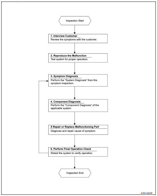
DETAILED FLOW
1. OBTAIN INFORMATION ABOUT SYMPTOM
Interview the customer to obtain as much information as possible about the conditions and environment under which the malfunction occurred.
>> GO TO 2.
2. CONFIRM THE SYMPTOM
Check the malfunction on the vehicle that the customer describes.
Inspect the relation of the symptoms and the condition when the symptoms occur.
>> GO TO 3.
3. IDENTIFY THE MALFUNCTIONING SYSTEM WITH SYMPTOM DIAGNOSIS
Use Symptom diagnosis from the symptom inspection result in step 2 and then identify where to start performing the diagnosis based on possible causes and symptoms. Refer to WW-46, "Symptom Table".
>> GO TO 4.
4. PERFORM THE COMPONENT DIAGNOSIS OF THE OF THE APPLICABLE SYSTEM
Perform the diagnosis with Component diagnosis of the applicable system.
>> GO TO 5.
5. REPAIR OR REPLACE THE MALFUNCTIONING PARTS
Repair or replace the specified malfunctioning parts.
>> GO TO 6.
6. FINAL CHECK
Check that malfunctions are not reproduced when obtaining the malfunction information from the customer, referring to the symptom inspection result in step 2.
Are the malfunctions corrected? YES >> Inspection End.
NO >> GO TO 3.
 Wiring diagram
Wiper and washer system
Wiring diagram - with intelligent key
Wiring diagram - without intelligent key
...

Other materials:
Symptom diagnosis
Nissan vehicle immobilizer systemnats
symptoms
Symptom Table
Note:
Before performing the diagnosis in the following table, check
“SEC-171, "Work Flow"”.
Check that vehicle is under the condition shown in “Conditions of
vehicle” before starting diagnosis, ...
Basic inspection
Diagnosis and repair workflow
Trouble diagnosis flow chart
Trouble diagnosis procedure
Interview with customer
Interview with the customer is important to detect the root cause of can
communication system errors and to
understand vehicle condition and symptoms for proper trouble diagnosi ...
Manual operation
Fan speed control
Press the fan control buttons to
manually
control the fan speed.
Press the AUTO button to return to automatic
control of the fan speed.
Air recirculation
Press the air recirculation
button to recirculate
interior air inside the vehicle. The
indicator light on the b ...
