Nissan Sentra Service Manual: Basic inspection
Diagnosis and repair workflow
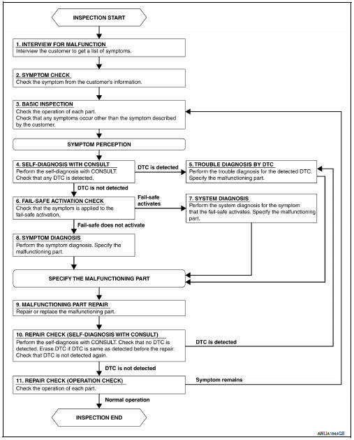
Work flow
OVERALL SEQUENCE
DETAILED FLOW
1.INTERVIEW FOR MALFUNCTION
Find out what the customer's concerns are.
>> GO TO 2.
2.SYMPTOM CHECK
Verify the symptom from the customer's information.
>> GO TO 3.
3.BASIC INSPECTION
Check the operation of each part. Check that any concerns occur other than those mentioned in the customer interview.
>> GO TO 4.
4.SELF-DIAGNOSIS WITH CONSULT
Perform the self-diagnosis with CONSULT. Check that any DTC is detected.
Is any DTC detected? YES >> GO TO 5.
NO >> GO TO 6.
5.TROUBLE DIAGNOSIS BY DTC
Perform the trouble diagnosis for the detected DTC. Specify the malfunctioning part.
>> GO TO 9.
6.FAIL-SAFE ACTIVATION CHECK
Determine if the customer's concern is related to fail-safe activation.
Does the fail-safe activate? YES >> GO TO 7.
NO >> GO TO 8.
7.SYSTEM DIAGNOSIS
Perform the system diagnosis for the system in which the fail-safe activates. Specify the malfunctioning part.
>> GO TO 9.
8.SYMPTOM DIAGNOSIS
Perform the symptom diagnosis, refer to INL-51, "Symptom Table". Specify the malfunctioning part.
>> GO TO 9.
9.MALFUNCTION PART REPAIR
Repair or replace the malfunctioning part.
>> GO TO 10.
10.REPAIR CHECK (SELF-DIAGNOSIS WITH CONSULT)
Perform the self-diagnosis with CONSULT. Verify that no DTCs are detected. Erase all DTCs detected prior to the repair. Verify that DTC is not detected again.
Is any DTC detected? YES >> GO TO 5.
NO >> GO TO 11.
11.REPAIR CHECK (OPERATION CHECK)
Check the operation of each part.
Does it operate normally? YES >> Inspection End.
NO >> GO TO 3.
 Wiring diagram
Interior room lamp control system
Wiring diagram
Illumination
Wiring diagram
...

Other materials:
Removal and installation
A/C SWITCH ASSEMBLY
Removal and Installation
REMOVAL
Remove the CVT shift selector finisher (CVT: RE0F11A). Refer to TM-253,
"Removal and Installation".
Remove the MT shift selector finisher (6MT: RS6F94R). Refer to TM-22,
"Removal and Installation".
Remove the A/ ...
Tire labeling
Federal law requires tire manufacturers to
place standardized information on the
sidewall of all tires. This information identifies
and describes the fundamental
characteristics of the tire and also provides
the tire identification number (TIN)
for safety standard certification. The TIN
can b ...
Battery terminal with fusible link
Exploded view
Battery terminal with fusible link
Harness connector
Removal and installation
Removal
Loosen the battery terminal nuts and disconnect both battery negative and
positive terminals. Refer to
pg-50, "exploded view".
Caution:
To prevent damage to the parts, di ...
