Nissan Sentra Service Manual: Basic inspection
Diagnosis and repair work flow
Work flow
OVERALL SEQUENCE
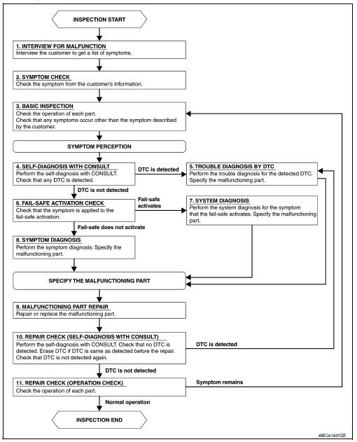
DETAILED FLOW
1.INTERVIEW FOR MALFUNCTION
Find out what the customer's concerns are.
>> GO TO 2
2.SYMPTOM CHECK
Verify the symptom from the customer's information.
>> GO TO 3
3.BASIC INSPECTION
Check the operation of each part. Check that any concerns occur other than those mentioned in the customer interview.
>> GO TO 4
4.SELF-DIAGNOSIS WITH CONSULT
Perform the self diagnosis with CONSULT. Check that any DTC is detected.
Is any DTC detected? YES >> GO TO 5
NO >> GO TO 6
5.TROUBLE DIAGNOSIS BY DTC
Perform the trouble diagnosis for the detected DTC. Specify the malfunctioning part.
>> GO TO 9
6.FAIL-SAFE ACTIVATION CHECK
Determine if the customer's concern is related to fail-safe activation.
Does the fail-safe activate? YES >> GO TO 7
NO >> GO TO 8
7.SYSTEM DIAGNOSIS
Perform the system diagnosis for the system in which the fail-safe activates. Specify the malfunctioning part.
>> GO TO 9
8.SYMPTOM DIAGNOSIS
Perform the symptom diagnosis. Specify the malfunctioning part.
>> GO TO 9
9.MALFUNCTION PART REPAIR
Repair or replace the malfunctioning part.
>> GO TO 10
10.REPAIR CHECK (SELF-DIAGNOSIS WITH CONSULT)
Perform the self diagnosis with CONSULT. Verify that no DTCs are detected. Erase all DTCs detected prior to the repair. Verify that DTC is not detected again.
Is any DTC detected? YES >> GO TO 5
NO >> GO TO 11
11.REPAIR CHECK (OPERATION CHECK)
Check the operation of each part.
Does it operate normally?
YES >> Inspection End.
NO >> GO TO 3
 Wiring diagram
Headlamp
Wiring diagram
Daytime light system
Wiring diagram
Auto light system
Wiring diagram
Front fog lamp
Wiring diagram
...

Other materials:
How to Follow Test Groups in Trouble Diagnosis
Test group number and test group title
Test group number and test group title are shown in the upper portion of
each test group.
Work and diagnosis procedure
Start to diagnose a problem using procedures indicated in enclosed test
groups.
Questions and results
...
To protect your vehicle from corrosion
Wash and wax your vehicle often to keep the
vehicle clean.
Always check for minor damage to the paint
and repair it as soon as possible.
Keep drain holes at the bottom of the doors
open to avoid water accumulation.
Check the underbody for accumulation of
sand, dirt or salt. If prese ...
Precaution for Work
When removing or disassembling each component, be careful not to damage
or deform it. If a component
may be subject to interference, be sure to protect it with a shop cloth.
When removing (disengaging) components with a screwdriver or similar
tool, be sure to wrap the component
with a ...
