Nissan Sentra Service Manual: B terminal circuit
Description
Terminal “B” is constantly supplied with battery power.
Diagnosis Procedure
Regarding Wiring Diagram information, refer to STR-10, "Wiring Diagram" (with Intelligent Key system) or STR-15, "Wiring Diagram" (without Intelligent Key system).
CAUTION:
Perform diagnosis under the condition that the engine cannot start by the following procedure.
- Remove fuel pump fuse.
- Crank or start the engine (where possible) until the fuel pressure is released.
1.CHECK “B” TERMINAL CIRCUIT
- Turn ignition switch OFF
- Check that starter motor B” terminal connection is clean and tight.
- Check voltage between starter motor connector F27 and ground.
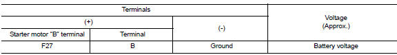
Is the inspection result normal? YES >> GO TO 2.
NO >> Check harness between battery and starter motor for open circuit.
2.CHECK BATTERY CABLE CONNECTION STATUS (VOLTAGE DROP TEST)
- Shift selector lever to P (Park) or N (Neutral) position (CVT Models) or the clutch pedal is depressed (M/T Models).
- Check voltage between battery positive terminal and starter motor B terminal.
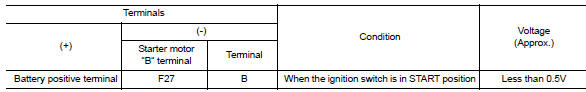
Is the inspection result normal? YES >> GO TO 3.
NO >> Check harness between the battery and starter motor for continuity.
3.CHECK GROUND CIRCUIT STATUS (VOLTAGE DROP TEST)
- Shift selector lever to P (Pack) or N (Neutral) position (CVT Models) or the clutch pedal is depressed (M/T Models).
- Check voltage between starter motor case and battery negative terminal.
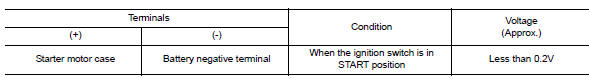
Is the inspection result normal? YES >> “B” terminal circuit is OK. Further inspection is necessary. Refer to STR-20, "Work Flow (With GR8-1200 NI)" or STR-24, "Work Flow (Without GR8-1200 NI)".
NO >> Check the starter motor case to engine mounting for high resistance.

 S connector circuit
Description
The starter motor magnetic switch is supplied with power when the ignition
switch is turned to the START position
while the selector lever is in the P (Park) or N (Neutral) position (C ...
Other materials:
Moonroof unit assembly
Inspection
WIND DEFLECTOR
Open glass lid fully
Visually check for proper installation, damaged/deteriorated components,
or foreign objects within mechanism.
Correct as required for smooth operation.
Check for grease at the wind deflector arm (1) and pivot areas. If
necessary, apply ...
Symptom diagnosis
Squeak and rattle trouble diagnoses
Work Flow
CUSTOMER INTERVIEW
Interview the customer if possible, to determine the conditions that exist
when the noise occurs. Use the Diagnostic
Worksheet during the interview to document the facts and conditions when the
noise occurs and any
custom ...
P1588 G Sensor
DTC Logic
DTC DETECTION LOGIC
DTC
CONSULT screen terms
(Trouble diagnosis content)
DTC detection condition
Possible causes
P1588
G Sensor
(Gravity Sensor Circuit)
When the following diagnosis conditions are
satisfied and the detection conditi ...
