Nissan Sentra Service Manual: B0096 Front side air bag satellite sensor RH
Description
DTC B0096 FRONT SATELLITE SENSOR RH
The front side air bag satellite sensor RH is wired to the air bag diagnosis sensor unit. The air bag diagnosis sensor unit will monitor the front side air bag satellite sensor RH for internal failures and its circuits for communication errors.
PART LOCATION
Refer to SRC-5, "Component Parts Location".
DTC Logic
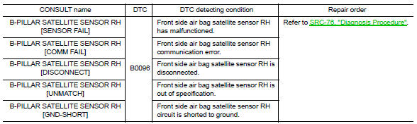
DTC DETECTION LOGIC
With CONSULT
DTC CONFIRMATION PROCEDURE (With CONSULT)
1.CHECK SELF-DIAG RESULT
- Turn ignition switch ON.
- Check for DTC using CONSULT.
Is the DTC detected? YES (Current DTC)>>Refer to SRC-76, "Diagnosis Procedure".
YES (Past DTC)>>GO TO 2.
NO >> Inspection End.
2.ERASE SELF-DIAG RESULT
Erase the DTC using CONSULT.
Can the DTC be erased? YES >> Inspection End.
NO >> Refer to SRC-76, "Diagnosis Procedure".
DTC CONFIRMATION PROCEDURE (Without CONSULT)
1.CHECK SELF-DIAG RESULT
- Turn ignition switch ON.
- Check the air bag warning lamp status. Refer to SRC-17, "Trouble Diagnosis without CONSULT".
NOTE:
SRS will not enter diagnosis mode if no malfunction is detected in user mode.
Is the DTC detected? YES >> Refer to SRC-76, "Diagnosis Procedure".
NO >> Inspection End.
Diagnosis Procedure
1.HARNESS CONNECTOR
Visually inspect all applicable harness connectors for the following:
- Visible damage to connector or terminal
- Loose terminal
- Poor connection
NOTE:
All harness connectors should be inspected from the air bag diagnosis sensor unit to the end component (including any in-line connectors).
Is the inspection result normal? YES >> GO TO 2.
NO >> Perform one of the following repairs:
- Visible damage: Replace the harness.
- Loose terminal: Secure the terminal
- Poor connection: Secure the connection.
2.CONFIRM DTC
- Reconnect all harness connectors.
- Turn ignition switch ON.
- Check for DTC using CONSULT.
Is DTC still current? YES >> GO TO 3.
NO >> Refer to GI-39, "Intermittent Incident".
3.WIRING HARNESS
Check the wiring harness for visible damage.
NOTE:
The entire wiring harness should be inspected from the air bag diagnosis sensor unit to the end component (including any in-line connectors).
Is the inspection result normal? YES >> GO TO 4.
NO >> Replace the harness.
4.CONFIRM DTC
- Reconnect all harness connectors.
- Turn ignition switch ON.
- Check for DTC using CONSULT.
Is DTC still current? YES >> GO TO 5.
NO >> Refer to GI-39, "Intermittent Incident".
5.FRONT SIDE AIR BAG SATELLITE SENSOR RH
- Replace the front side air bag satellite sensor RH. Refer to SR-26, "Removal and Installation".
- Turn ignition switch ON.
- Check for DTC using CONSULT.
Is DTC still current? YES >> GO TO 6.
NO >> Clear DTC. Inspection End.
6.AIR BAG DIAGNOSIS SENSOR UNIT
- Replace the air bag diagnosis sensor unit. Refer to SR-28, "Removal and Installation".
- Turn ignition switch ON.
- Check for DTC using CONSULT.
Is DTC still current? YES >> GO TO 7.
NO >> Clear DTC. Inspection End.
7.RELATED HARNESS
Replace the related harness.
>> END
 B0094 Crash zone sensor
Description
DTC B0094 CRASH ZONE SENSOR
The crash zone sensor is wired to the air bag diagnosis sensor unit. The air
bag diagnosis sensor unit will
monitor for opens and shorts in detected lines ...
 B0097 Rear side air bag satellite sensor RH
Description
DTC B0097 REAR SATELLITE SENSOR RH
The rear side air bag satellite sensor RH is wired to the air bag diagnosis
sensor unit. The air bag diagnosis
sensor unit will monitor the rear sid ...
Other materials:
Front wiper motor hi circuit
Component function check
1. Check front wiper hi operation
Ipdm e/r auto active test
Start ipdm e/r auto active test. Refer to ww-15, "diagnosis description"
(with intelligent key system) or
ww-19, "diagnosis description" (without intelligent key system).
Check tha ...
Component parts
Engine control system
ENGINE CONTROL SYSTEM :Component Parts Location
Engine room compartment
No.
Component
Function
1
IPDM E/R
IPDM E/R control the internal relays and the actuators.
When CAN communication with ECM is impossible, IPDM
E/R performs fail-sa ...
System description
Component parts
Component parts location
Instrument lower finisher
Component description
Eco mode switch
The ECO mode switch is installed to the instrument lower finisher.
When the eco mode indicator lamp on the combination meter is
off and the eco mode switch is pressed, t ...
