Nissan Sentra Service Manual: Air conditioning cut control
AIR CONDITIONING CUT CONTROL : System Description
SYSTEM DIAGRAM
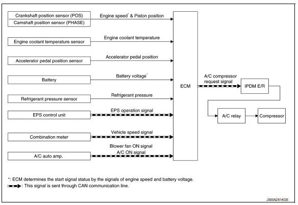
INPUT/OUTPUT SIGNAL CHART
| Sensor | Input Signal to ECM | ECM function | Actuator | |
| Crankshaft position sensor (POS) | Engine speed* Piston position | Air conditioner cut control | IPDM E/R
↓ Air conditioner relay ↓ Compressor |
|
| Camshaft position sensor (PHASE) | ||||
| Engine coolant temperature sensor | Engine coolant temperature | |||
| Accelerator pedal position sensor | Accelerator pedal position | |||
| Battery | Battery voltage* | |||
| Refrigerant pressure sensor | Refrigerant pressure | |||
| EPS control unit | CAN communication | EPS operation signal | ||
| Combination meter | CAN communication | Vehicle speed signal | ||
| A/C auto amp. | CAN communication |
|
||
*: ECM determines the start signal status by the signals of engine speed and battery voltage.
SYSTEM DESCRIPTION
This system improves engine operation when the air conditioner is used.
Under the following conditions, the air conditioner is turned off.
- When the accelerator pedal is fully depressed.
- When cranking the engine.
- At high engine speeds.
- When the engine coolant temperature becomes excessively high.
- When operating power steering during low engine speed or low vehicle speed.
- When engine speed is excessively low.
- When refrigerant pressure is excessively low or high.
 Fuel filler cap warning system
SYSTEM DIAGRAM
SYSTEM DESCRIPTION
The fuel filler cap warning system alerts the driver to the prevention of the
fuel filler being left uncapped and
malfunction occurrences after refueling, by ...
 Cooling fan control
SYSTEM DIAGRAM
SYSTEM DESCRIPTION
ECM controls cooling fan speed corresponding to vehicle speed, engine coolant
temperature, refrigerant pressure,
air conditioner ON signal. Then control syst ...
Other materials:
Basic inspection
Diagnosis and repair work flow
Work flow
OVERALL SEQUENCE
DETAILED FLOW
1.GET INFORMATION FOR SYMPTOM
Get detailed information from the customer about the symptom (the
condition and the environment when
the incident/malfunction occurs).
Check operation condition of the function th ...
Illumination control switch signal circuit
Diagnosis procedure
Regarding wiring diagram information, refer to mwi-28, "wiring diagram".
1.Check combination meter input signal
Turn ignition switch on.
Check voltage between the following terminals of the illumination
control switch.
Is the inspection result normal?
...
Power supply and ground circuit
Combination meter
COMBINATION METER : Diagnosis Procedure
Regarding Wiring Diagram information, refer to MWI-28, "Wiring Diagram".
1.Check fuses
Check that the following fuses are not blown.
Is the fuse blown?
Yes >> replace the blown fuse after repairing the affected circu ...
