Nissan Sentra Service Manual: Air cleaner and air duct
Exploded View
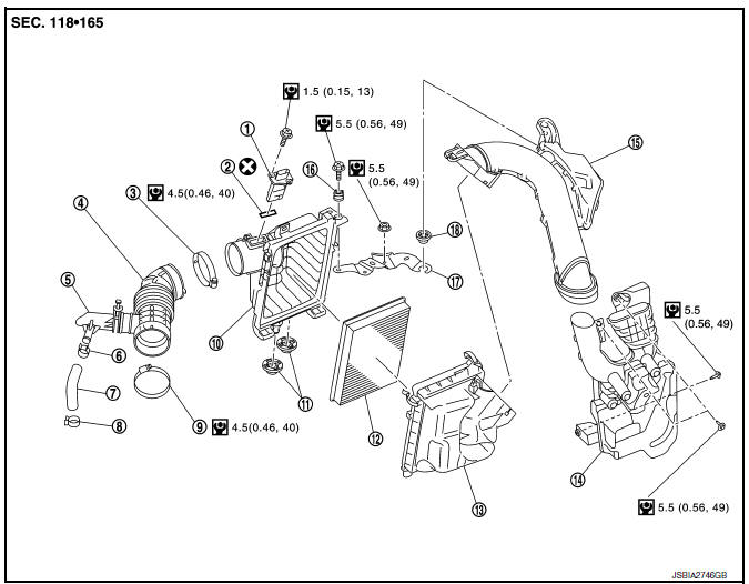
- Mass air flow sensor
- Mass air flow gasket
- Clamp
- Air duct (suction side)
- Resonator
- Clamp
- PCV hose
- Clamp
- Clamp
- Air cleaner cover
- Mounting rubber
- Air cleaner filter
- Air cleaner body
- Air duct inlet (lower)
- Air duct inlet (upper)
- Mounting rubber
- Bracket
- Grommet
Removal and Installation
REMOVAL
NOTE:
Mass air flow sensor is removable under the car-mounted condition.
- Remove engine room cover. Refer to EM-24, "Exploded View".
- Remove air duct inlet (upper).
- Remove air cleaner filter from the air cleaner cover.
- Disconnect mass air flow sensor harness connector, and remove harness clamp from air cleaner body assembly.
- Disconnect PCV hose and transaxle breather hose.
- Remove air cleaner body.
- Remove air duct (suction side).
- Add matching marks if necessary for easier installation.
- Remove air cleaner cover.
- Remove mass air flow sensor from air cleaner cover, if necessary.
CAUTION:
Handle the mass air flow sensor with following cares.
- Do not shock the mass air flow sensor.
- Do not disassemble the mass air flow sensor.
- Do not touch the sensor of the mass air flow sensor.
- Remove air duct inlet (lower) with the following procedure.
- Remove front combination lamp (LH). Refer to EXL-119, "Exploded View".
- Remove air duct inlet (lower).
INSTALLATION
CAUTION:
Do not reuse O-rings.
Installation is in the reverse order of removal.
- Align marks. Attach each joint. Screw clamps firmly.
- Tabs shall be fixed after inserting air cleaner body assembly protrusion to air cleaner case notch hole.
- Make sure whether air cleaner body has been firmly installed by shaking it.
Inspection
INSPECTION AFTER REMOVAL
Inspect air duct (suction side), air duct inlet (upper), air duct inlet (lower) and resonator for crack or tear.
- If anything is found, replace air duct (suction side), air duct inlet (upper), air duct inlet (lower) and resonator.
 Engine room cover
Exploded View
Engine room cover
Mounting rubber (Black)
Mounting rubber (Gray)
Removal and Installation
REMOVAL
CAUTION:
Do not damage or scratch engine room cover when installing o ...
 Intake manifold
Exploded View
Clamp
PCV hose
Bracket
Intake manifold gasket
Intake manifold
Mount rubber
Clamp
EVAP hose
EVAP canister purge volume
control solenoid valve
Electric throttl ...
Other materials:
DTC/circuit diagnosis
U1000 can comm
Description
Refer to LAN-7, "CAN COMMUNICATION SYSTEM : System Description".
Dtc logic
DTC DETECTION LOGIC
NOTE:
U1000 can be set if a module harness was disconnected and reconnected,
perhaps during a repair. Confirm
that there are actual CAN diagnostic symptoms a ...
Removal and installation
Av control unit
Exploded view
AV control unit
Av control unit bracket (lh)
AV control unit bracket (RH)
Removal and installation
Removal
Caution:
Remove battery terminal and av control unit after a lapse of 30
seconds or more after turning the
ignition switch off.
Before ...
System
CVT CONTROL SYSTEM
CVT CONTROL SYSTEM : System Diagram
CVT CONTROL SYSTEM : System Description
DESCRIPTION
CVT detects the vehicle driving status from switches, sensors and
signals, and controls the vehicle so that
the optimum shift position and shift timing may always be achieved ...
