Nissan Sentra Service Manual: Abs actuator and electric unit (control unit)
Exploded View
-
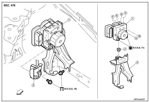
ABS actuator and electric unit (control unit)
-
ABS actuator and electric unit (control unit) harness connector
-
Bushing
-
Bracket
-
To master cylinder secondary side
-
To master cylinder primary side
-
To rear LH caliper
-
To front RH caliper
-
To front LH caliper
-
To rear RH caliper
 Front
Front
Removal and Installation
REMOVAL
-
Disconnect battery negative terminal. Refer to PG-50, "Exploded View".
-
Drain brake fluid. Refer to BR-17, "Drain and Refill".
-
Remove the cowl top. Refer to EXT-26, "Removal and Installation".
-
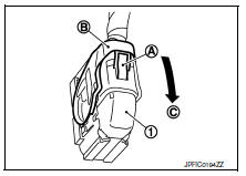
Disconnect ABS actuator and electric unit (control unit) harness connector (1), follow the procedure described below.
-
Push the pawl (A).
-
Move the lever (B) in the direction (C) until locked.
-
Disconnect ABS actuator and electric unit (control unit) harness connector.
-
Loosen flare nut of brake tube using a flare nut wrench, and then remove brake tube from ABS actuator and electric unit (control unit). Refer to BR-25, "FRONT : Exploded View".
-
Remove ABS actuator and electric unit (control unit) and bracket.
-
Remove bracket and bushing from ABS actuator and electric unit (control unit).
INSTALLATION
Installation is in the reverse order of removal.
-
When replacing with a new ABS actuator and electric unit (control unit), do not remove the protector of the brake tube mounting hole until right before the brake tube is installed.
-
When installing brake tube, tighten to the specified torque using a flare nut torque wrench so that flare nut and brake tube are not damaged. Refer to BR-25, "FRONT : Exploded View".
-
Do not remove and install ABS actuator and electric unit (control unit) by holding actuator harness.
-
Bleed air from brake piping after installation. Refer to BR-17, "Bleeding Brake System".
-
Do not apply excessive impact to actuator, such as by dropping it.
-
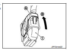
After installing the ABS actuator and electric unit (control unit) harness connector (1), move the lever (A) in the direction (B) to secure the locking.
 Sensor rotor
Front sensor rotor
FRONT SENSOR ROTOR : Removal and Installation
The front wheel sensor rotor is an integral part of the wheel
hub and bearing assembly and cannot be disassembled.
Refer to FAX- ...
 VDC off switch
Removal and Installation
REMOVAL
Remove the instrument lower panel LH. Refer to IP-21,
"Removal and Installation".
Remove the switch plate screws and remove the switch plate. ...
Other materials:
Cooling fan control
SYSTEM DIAGRAM
SYSTEM DESCRIPTION
ECM controls cooling fan speed corresponding to vehicle speed, engine coolant
temperature, refrigerant pressure,
air conditioner ON signal. Then control system has 3-step control
[HIGH/LOW/OFF].
Cooling Fan Operation
Cooling Fan Relay Operation
Whe ...
Unit disassembly and assembly
OIL PUMP
O-ring
Oil pan (upper)
Oil level gauge guide
O-ring
Oil level gauge
Oil pump chain tensioner
Oil pump drive chain
Crankshaft sprocket
Oil pump sprocket
Oil pump
Drain plug washer
Drain plug
Oil pan (lower)
Oil filter
Connector bolt
Crankshaft position s ...
Unit disassembly and assembly
TORQUE CONVERTER AND CONVERTER HOUSING OIL SEAL
Exploded View
Transaxle assembly
Torque converter
Converter housing oil seal
: Apply CVT Fluid
Disassembly
Remove transaxle assembly.
Remove torque converter.
CAUTION:
Do not damage the bushing on the inside of torque con ...
