Nissan Sentra Service Manual: Removal and installation
EXHAUST SYSTEM
Exploded View
- Sub muffler
- Spring
- Mounting rubber
- Seal bearing
- Catalyst shroud (upper)
- Seal bearing
- Exhaust front tube
- Spring
- Catalyst shroud (lower)
- Clamp
- Heated oxygen sensor 2
- Ring gasket
- Mounting rubber
- Main muffler
- Exhaust finisher (if equipped)
- To exhaust manifold
Removal and Installation
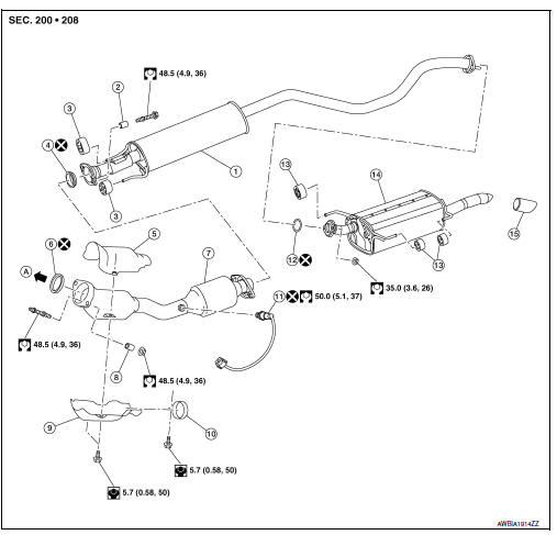
REMOVAL
- Disconnect each joint and mounting rubber.
- Remove heated oxygen sensor 2 (1) using Tool (A).
Tool number : KV10114400 (J-38365)
CAUTION:
- Discard any heated oxygen sensor which has been dropped from a height of more than 0.5 m (19.7 in) onto a hard surface such as a concrete floor; use a new one.
- Before installing new heated oxygen sensor, clean exhaust system threads using oxygen sensor thread cleaner and approved anti-seize lubricant.
Oxygen sensor thread cleaner : J-43897-12
Oxygen sensor thread cleaner : J-43897-18
INSTALLATION
Installation is in the reverse order of removal.
CAUTION:
- Always replace seal bearings with new ones when reassembling.
- Discard any heated oxygen sensor 2 which has been dropped onto a hard surface such as a concrete floor. Use a new one.
- Before installing a new heated oxygen sensor 2, clean exhaust system threads using the oxygen sensor thread cleaner and apply anti-seize lubricant.
- Do not over tighten heated oxygen sensor 2. Doing so may cause damage to the heated oxygen sensor 2, resulting in the đ▓đéĐÜMILđ▓đéĐť coming on.
- Prevent rust preventives from adhering to the sensor body.
- If heat insulator is badly deformed, repair or replace it. If deposits such as mud pile up on the heat insulator, remove them.
- When installing heat insulator avoid large gaps or interference between heat insulator and each exhaust pipe.
- Remove deposits from the sealing surface of each connection. Connect them securely to avoid gas fume leaks.
- When installing each mounting rubber, use silicon oil to avoid twisting.
- Temporarily tighten nuts and bolts. Check each part for unusual interference and mounting rubber interference, and then tighten them to the specified torque.
- When installing each mounting rubber, avoid twisting or unusual extension in up/down, front/rear and right/left directions.
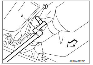
Exhaust Manifold to Exhaust Front Tube
- Securely insert seal bearing (2) into exhaust manifold (1) in the direction shown.
- Spring
- Nut
- Stud bolt
- Exhaust front tube
CAUTION:
Be careful not to damage seal bearing surface when installing.
- Install spring and tighten nut.
CAUTION:
- Fasten stud bolts to the flange of exhaust manifold side to the specified torque before installing nuts.
- Ensure springs are seated correctly on the flange and not sitting on protrusion (A).
- Be careful that stud bolt does not interfere with mounting hole of
exhaust front tube (
 ).
).
- After installing, check that stud bolt does not interfere with mounting hole of exhaust front tube.
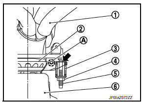
Exhaust Front Tube to Center Muffler
- Securely insert seal bearing (2) into exhaust front tube (1) in the direction shown.
- Spring
- Bolt
- Center muffler
CAUTION:
Be careful not to damage seal bearing surface when installing.
- Install spring and tighten bolt.
CAUTION:
- Ensure springs are seated correctly on the flange and not sitting on protrusion (A).
- Be careful that bolt does not interfere with mounting hole of
center muffler (
 ).
).
- After installing, check that bolt does not interfere with mounting hole of center muffler.
Inspection
INSPECTION AFTER INSTALLATION
- Check clearance between tail tube and rear bumper is even.
- With engine running, check exhaust tube joints for gas fume leaks and unusual noises.
- Check to ensure that mounting brackets and mounting rubbers are installed properly and free from undue stress. Improper installation could result in excessive noise and vibration.
 Periodic maintenance
EXHAUST SYSTEM
Inspection
Check exhaust pipes, muffler, and mounting for improper attachment,
leakage, cracks, damage or deterioration.
If anything is found, repair or replace damaged parts.
...
 Starting system
...
Other materials:
1110, C1170 ABS Actuator and electric unit (control unit)
DTC Logic
DTC DETECTION LOGIC
DTC
Display item
Malfunction detected condition
Possible cause
C1110
CONTROLLER FAILURE
When there is an internal malfunction in the ABS actuator
and electric unit (control unit).
ABS actuator and electric unit
(contr ...
Cleaning exterior
In order to maintain the appearance of your vehicle,
it is important to take proper care of it.
To protect the paint surfaces, please wash your
vehicle as soon as you can:
after a rainfall to prevent possible damage
from acid rain.
after driving on coastal roads.
when contaminants suc ...
Voice commands
Voice commands can be used to operate the
Bluetooth® Hands-Free Phone System. Press
the button and say ÔÇťPhoneÔÇŁ to bring
up the
phone command menu. The available options
are:
Call
Phonebook
Recent Calls
Send Text
Read Text
Select Phone
ÔÇťCallÔÇŁ
For more information on ...
