Nissan Sentra B18 (2020-2025) Service Manual: Precaution. Precautions
Precautions
Precautions for Supplemental Restraint System (srs) "air Bag" and "seat Belt Pre-Tensioner"
The Supplemental Restraint System such as “AIR BAG” and “SEAT BELT PRE-TENSIONER”, used along with a front seat belt, helps to reduce the risk or severity of injury to the driver and front passenger for certain types of collisions.
Information necessary to service the system safely is included in the “SRS AIR BAG” and “SEAT BELT” sections of this Service Manual.
Warning:
Always observe the following items for preventing accidental activation:
-
To avoid rendering the SRS inoperative, which could increase the risk of personal injury or death in the event of a collision that would result in air bag inflation, it is recommended that all maintenance and repair be performed by an authorized NISSAN/INFINITI dealer.
-
Improper repair, including incorrect removal and installation of the SRS, can lead to personal injury caused by unintentional activation of the system. For removal of Spiral Cable and Air Bag Module, see “SRS AIR BAG”.
-
Never use electrical test equipment on any circuit related to the SRS unless instructed to in this Service Manual. SRS wiring harnesses can be identified by yellow and/or orange harnesses or harness connectors.
PRECAUTIONS WHEN USING POWER TOOLS (AIR OR ELECTRIC) AND HAMMERS
Warning:
Always observe the following items for preventing accidental activation:
-
When working near the Air Bag Diagnosis Sensor Unit or other Air Bag System sensors with the ignition/power switch ON or engine running, never use air or electric power tools or strike near the sensor(s) with a hammer. Heavy vibration could activate the sensor(s) and deploy the air bag(s), possibly causing serious injury.
-
When using air or electric power tools or hammers, always switch the ignition/power switch OFF, disconnect the 12V battery or batteries, and wait at least 3 minutes before performing any service.
Precautions for Trouble Diagnosis
CAUTION:
Follow the instructions listed below. Failure to do this may cause damage to parts:
-
Never apply 7.0 V or more to the measurement terminal.
-
Use a tester with open terminal voltage of 7.0 V or less.
-
Turn the ignition switch OFF and disconnect the battery cable from the negative terminal when checking the harness.
Precautions for Harness Repair
-
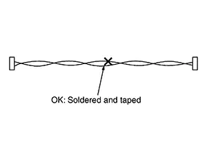
Solder the repaired area and wrap tape around the soldered area.
 Note:
Note: 
A fray of twisted lines must be within 110 mm (4.33 in).
-
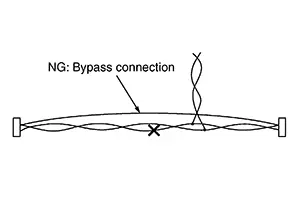
Bypass connection is never allowed at the repaired area.
 Note:
Note:
Bypass connection may cause CAN communication error. The spliced wire becomes separated and the characteristics of twisted line are lost.
-
Replace the applicable harness as an assembly if error is detected on the shield lines of CAN communication line.
Other materials:
Diagnosis description : system readiness
test (SRT) code
System Readiness Test (SRT) code is specified in Service $01 of SAE J1979/ISO
15031-5.
As part of an enhanced emissions test for Inspection & Maintenance (I/M),
certain states require the status of
SRT be used to indicate whether the ECM has completed self-diagnosis of major
emission s ...
P27a1-00 Electric Oil Pump
Dtc Description
DTC Description
DTC DETECTION LOGIC
DTC
CONSULT screen terms
(Trouble diagnosis
content)
DTC detection
conditi ...
Ipdm-e branch line circuit
Diagnosis Procedure
1.Check connector
Turn the ignition switch off.
Disconnect the battery cable from the negative terminal.
Check the terminals and connectors of the ipdm e/r for damage, bend and
loose connection (unit side
and connector side).
Is the inspection result normal?
Yes ...